Expansion valve

a technology of expansion valve and expansion shaft, which is applied in the direction of valve housing, valve operating means/release devices, lighting and heating apparatus, etc., can solve the problems of accelerating wear, generating wear debris, and body wear, so as to and prevent or reduce wear of the supporting par

Inactive Publication Date: 2016-12-08
TGK
View PDF3 Cites 0 Cited by
  • Summary
  • Abstract
  • Description
  • Claims
  • Application Information

AI Technical Summary

Benefits of technology

[0012]In this embodiment, the vibration-proof spring and the seal ring are positioned with the sliding portions of the shaft and the support part therebetween. As a result, the shaft is supported at two points by two shock absorbing members, which are the vibration-proof spring and the seal ring. This allows high coaxiality of the shaft with the support part to be maintained. Consequently, wear of the support part is prevented or reduced, and adhesion of wear debris to the shaft is thus prevented or reduced. Furthermore, since the seal ring is disposed on a relatively high pressure side (on the first passage side) with respect to the sliding portions, entry of foreign materials between the sliding portions is effectively prevented or reduced.

Problems solved by technology

The body may thus be worn by sliding of the shaft and generate wear debris.
This may cause uneven contact of the shaft with the support part or localized contact of the shaft with respective end positions of the support part, which may accelerate the wear.
Thus increased wear debris may adhere to the shaft and increase sliding resistance (friction), which may lower the actuation responsiveness of a valve section.

Method used


Image

  • Expansion valve
  • Expansion valve
  • Expansion valve

Examples


Embodiment Construction

[0017]The invention will now be described by reference to the preferred embodiments. This does not intend to limit the scope of the present invention, but to exemplify the invention.

[0018]An Embodiment of the present invention will now be described in detail with reference to the drawings. In the following description, for convenience of description, the positional relationship in each structure may be expressed with reference to how each structure is depicted in the drawings. Note that components that are substantially the same in the following embodiment and the modifications thereof will be designated by the same reference numerals and that redundant description thereof may be omitted as appropriate.

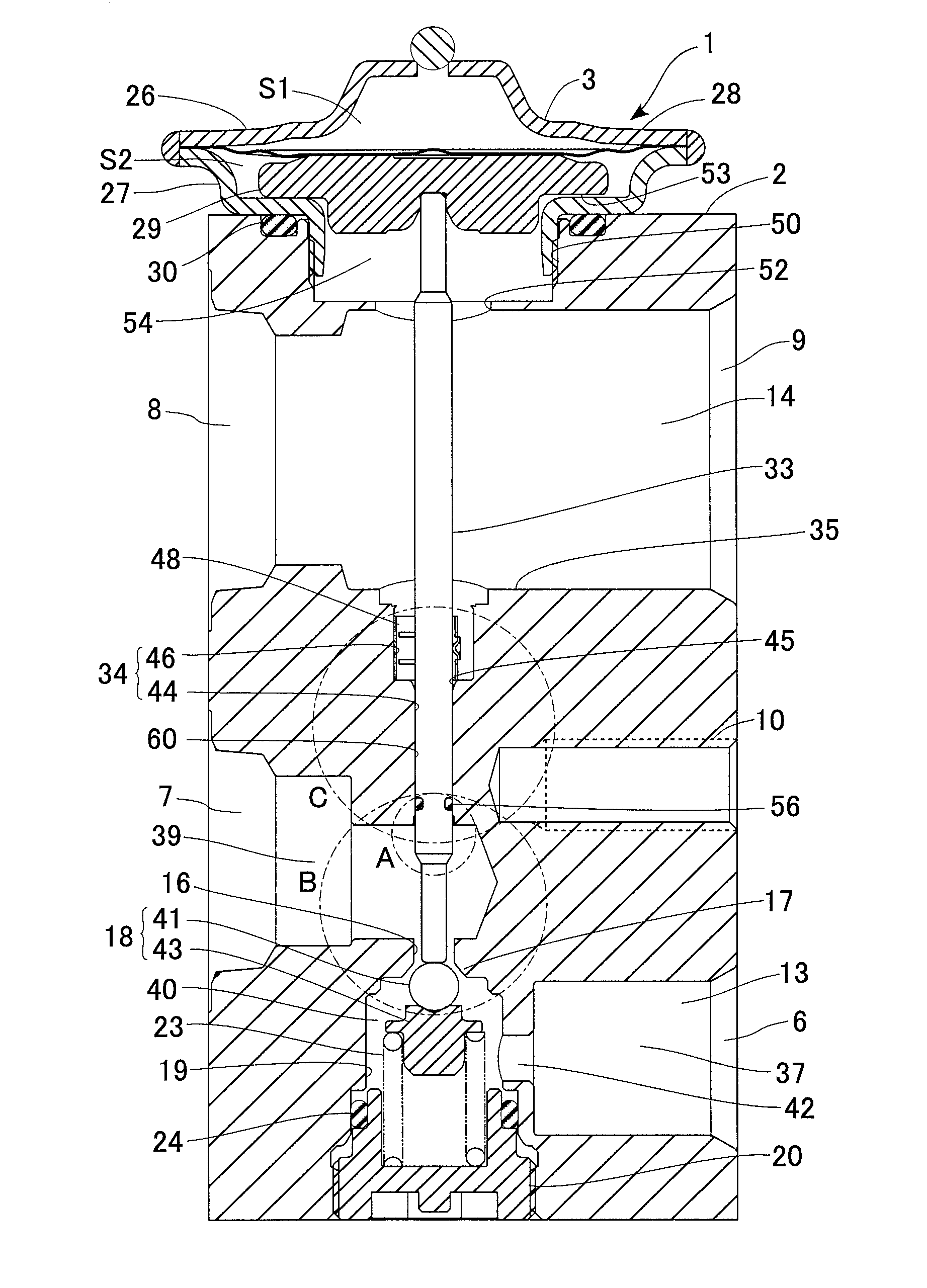
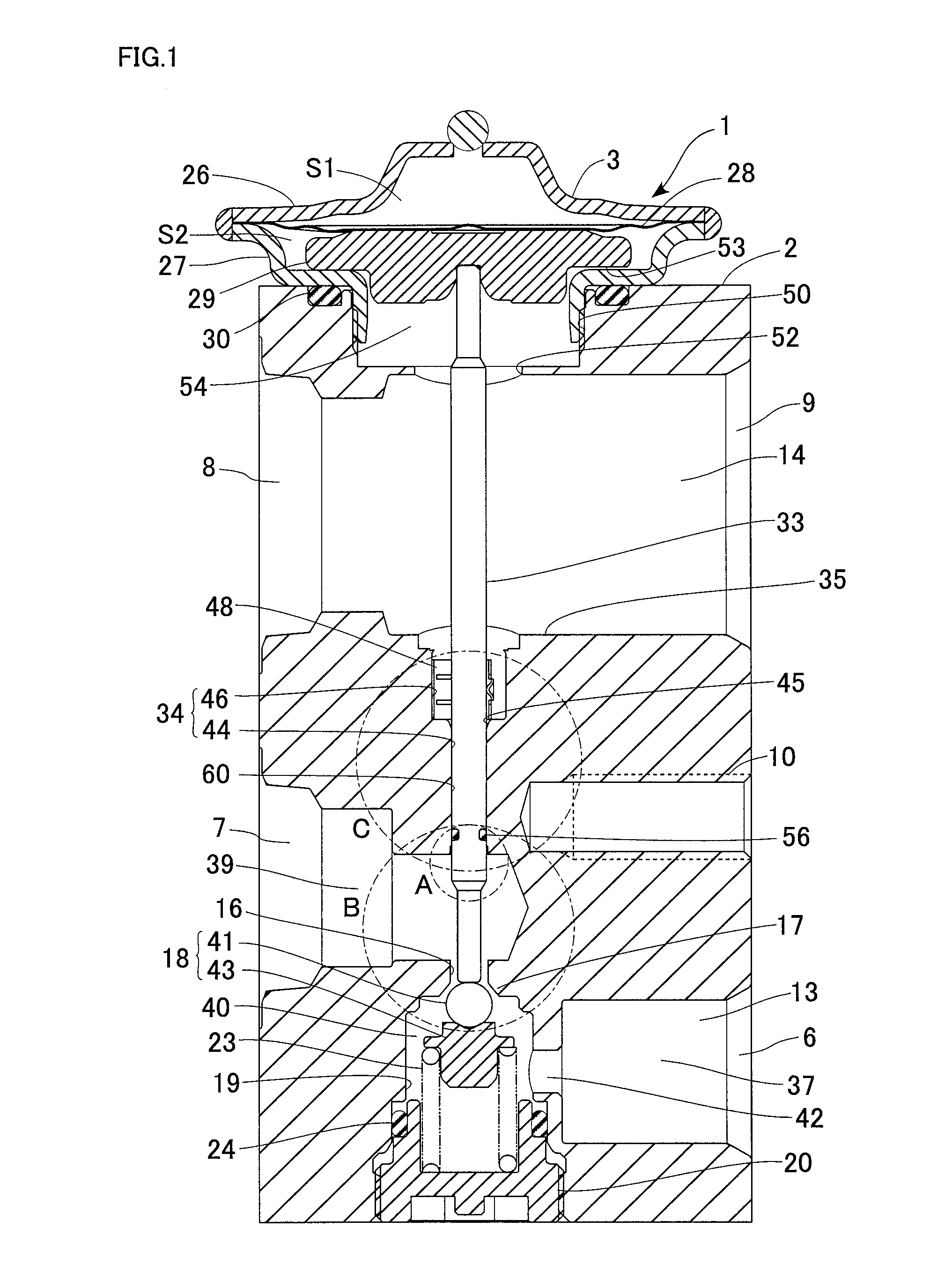
[0019]The embodiment embodies an expansion valve of the present invention in a form of a thermostatic expansion valve applicable to a refrigeration cycle in an automotive air conditioner. The refrigeration cycle includes a compressor for compressing a circulating refrigerant, a conden...


PUM


Abstract

An expansion valve includes: a body having an insertion hole in a partition separating a first passage from a second passage; a power element configured to generate a drive force for opening or closing a valve section; a shaft extending through the insertion hole and configured to transmit the drive force to a valve element; a vibration-proof spring coaxially supporting the shaft and biasing the shaft radially inward to apply a sliding resistance thereto; and a flexible O-ring supported by one of an inner surface of the support part defining the insertion hole and an outer surface of the shaft and being in close contact with the other thereof. The O-ring, sliding portions of the shaft and the support part, and the vibration-proof spring are arranged in this order from a first passage side toward a second passage side in an axial direction of the shaft.

Description

CLAIM OF PRIORITY[0001]This application claims priority to Japanese Patent Application No. 2015-113551, filed on Jun. 4, 2015, and is incorporated herein by reference.BACKGROUND OF THE INVENTION[0002]1. Field of the Invention[0003]The present invention relates to an expansion valve, and more particularly to a thermostatic expansion valve suitable for use in a refrigeration cycle.[0004]2. Description of the Related Art[0005]A refrigeration cycle in an automotive air conditioner generally includes a compressor for compressing a circulating refrigerant, a condenser for condensing the compressed refrigerant, an expansion valve for throttling and expanding the condensed liquid refrigerant and delivering the resulting spray of refrigerant, and an evaporator for cooling the air in a vehicle interior using evaporative latent heat of the refrigerant. The expansion valve is, for example, a thermostatic expansion valve that senses the temperature and the pressure of the refrigerant on the outl...

Claims


Application Information

Patent Timeline
Patent Type & Authority Applications(United States)
IPC IPC(8): F25B41/06F16K1/32F16K1/14F16K31/00F16K27/02
CPCF25B41/062F16K31/002F16K1/32F16K1/14F16K27/0245F25B2341/068F25B41/335F25B2341/0683F25B2500/13
Inventor SATAKE, RYOSUKEKANEKO, TAKESHI
Owner TGK
Why Eureka
Try Eureka