Hemostatic clip

a hemostatic clip and clip technology, applied in the field of medical equipment, to achieve the effect of improving clamping force, facilitating staggered, and effective reducing closing resistan

Active Publication Date: 2016-12-22
MICRO TECH (NANJING) CO LTD
View PDF11 Cites 41 Cited by
  • Summary
  • Abstract
  • Description
  • Claims
  • Application Information

AI Technical Summary

Benefits of technology

[0009]In the present invention, the engaged distal ends of the two clamping arms are matched in a serrated shape, so that two forceps heads are engaged synchronously to ensure the effectiveness after the clip is closed. After the engaged distal ends of the two clamping arms are closed, the end surfaces are spherical ones, so that the clip better passes through curves and protects the endoscopic tract.
[0017]Beneficial effects: the hemostatic clip of the present invention is simple and convenient to operate, and can rotate conveniently inside the human body according to the requirement of various angles; meanwhile, after the hemostatic clip is positioned successfully, it can be released through the operation rope, so that the hemostatic clip body is left inside the human body.

Problems solved by technology

However, the existing hemostatic clip is inconvenient to place and fix, so a hemostatic clip convenient to use is urgently needed.

Method used


Image

  • Hemostatic clip
  • Hemostatic clip
  • Hemostatic clip

Examples


embodiments

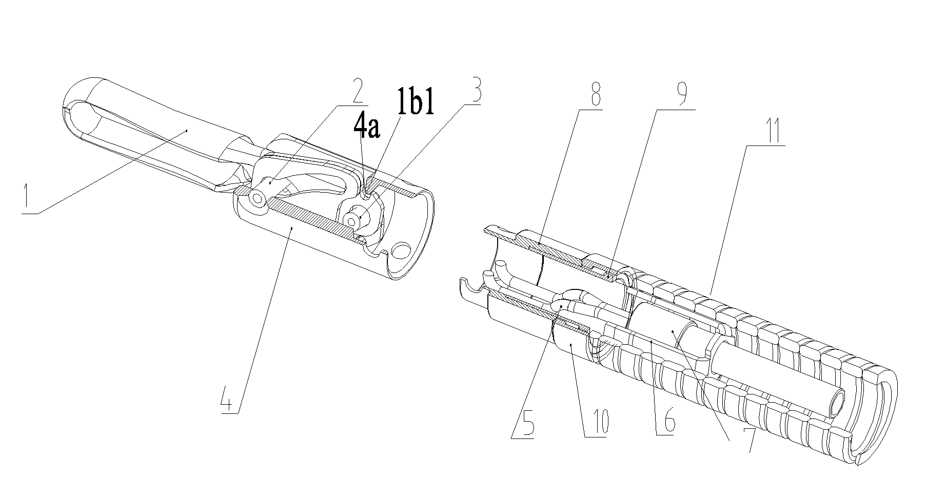
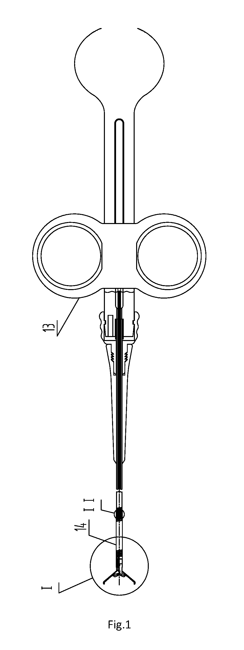
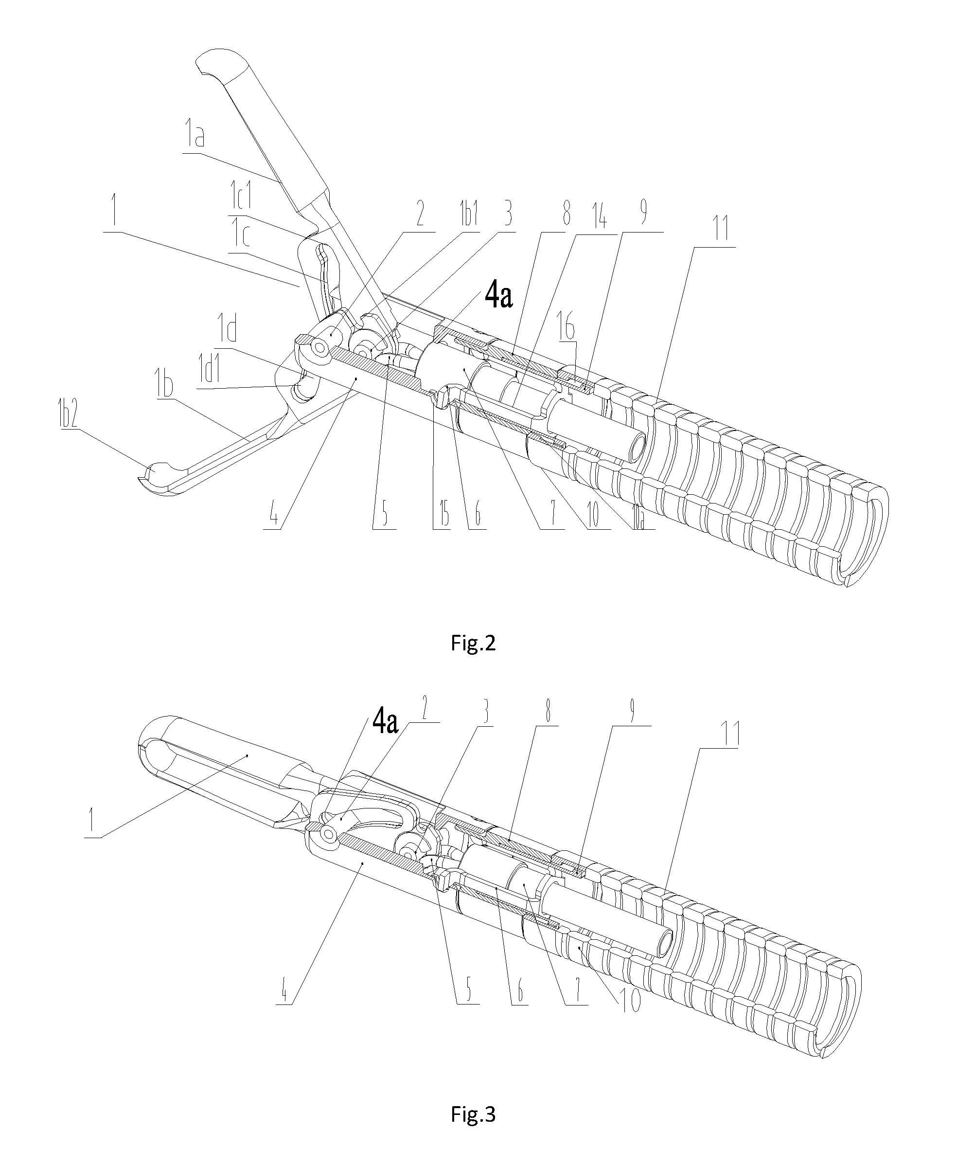
[0036]As shown in FIG. 1 and FIG. 2, the present invention discloses a hemostatic clip, including an outer sleeve assembly and a clamping assembly positioned inside the outer sleeve assembly, wherein the outer sleeve assembly includes a clip base 4, a transition cap 8, a fixed cap 10 and a distal end spring tube 11 which are sequentially connected; the clamping assembly includes a clip body 1, a steel wire buckle 5, a connector 7 and an operation rope 14 for connecting an operation handle 13 which are connected in sequence; and a fixed hinge pin 2 is arranged at the front end of the clip base, the clip body is composed of two clamping arms 1a and 1b, the tail ends of the two clamping arms are connected through a movable hinge pin 3, the middle part of each of the two clamping arms is provided with a chute 1c or 1d, and the engaged distal ends of the two clamping arms are matched in a serrated shape 1b2. As shown in FIG. 7, bent structures 1c1 and 1d1 are arranged at the tail ends of...


PUM


Abstract

A hemostatic clip comprises a clamping assembly and a clip base. The clamping assembly comprises a clip body and a steel wire buckle sequentially connected; a fixed hinge pin is arranged at the front end of the clip base, the clip body consists of two clamping arms, the tail ends of the two clamping arms are connected through a movable hinge pin, the middle part of each of the two clamping arms is provided with a chute, the fixed hinge pin penetrates through the chutes, and the two clamping arms reciprocate along the chutes so that the clip body can be opened and closed; a bent structure is arranged at the tail end of each chute; and when the clamping arms move to make the fixed hinge pin be located in the bent structures, the two clamping arms are located in the locked and closed position.

Description

[0001]This application is the U.S. national phase of International Application No. PCT / CN / 2014 / 081316 Filed on 30 Jun. 2014 which designated the U.S. and claims priority to Chinese Application Nos. CN201410222753.7 filed on 23 May, 2014, the entire contents of each of which are hereby incorporated by reference.FIELD OF THE INVENTION[0002]The present invention relates to medical equipment used inside human bodies, and particularly relates to a hemostatic clip capable of being conveniently separated and operated.BACKGROUND OF THE INVENTION[0003]In recent years, endoscopic hemostatic clips have become the most effective and most clinically valuable equipment for non-operational treatment of acute gastrointestinal tract hemorrhage of critical patients owing to the characteristics of low wound, high hemostatic speed, low re-bleeding rate, few complications, exact effect and the like. Hemostasis with a metal clip under an endoscope is one of the widely applicable hemostasis means, and the...

Claims


Application Information

Patent Timeline
Patent Type & Authority Applications(United States)
IPC IPC(8): A61B17/122A61B17/128
CPCA61B17/122A61B2017/12004A61B17/1285A61B17/128A61B17/08A61B2017/00473
Inventor JIN, HONGYANTANG, ZHIFAN, MINGQIAOSONG, RAN
Owner MICRO TECH (NANJING) CO LTD
Why Eureka
Try Eureka