Ammonia slip catalyst with low n2o formation

a slip catalyst and ammonia technology, applied in the field of ammonia slip catalysts, can solve the problems of reducing the n2 yield of ammonia, so as to improve the n2 yield. , the effect of improving the n2 yield

Pending Publication Date: 2016-12-22
JOHNSON MATTHEY PLC
View PDF3 Cites 31 Cited by
  • Summary
  • Abstract
  • Description
  • Claims
  • Application Information

AI Technical Summary

Benefits of technology

[0005]In the first aspect, the invention relates to a catalyst comprising a combination of platinum on a support with low ammonia storage and a first SCR catalyst, preferably a Cu-SCR catalyst or an Fe-SCR catalyst. The support with low ammonia storage can be a siliceous support. The siliceous support can comprise a silica or a zeolite with silica-to-alumina ratio of at least 100. The combination of platinum on a support with low ammonia storage is either (1) a blend of platinum on a support with low ammonia storage with a first SCR catalyst, or (2) a bi-layer having a top layer comprising a first SCR catalyst and a bottom layer comprising platinum on a support with low ammonia storage, where the bottom layer is positioned on a substrate or on a third SCR catalyst located between the bottom layer and the third SCR catalyst. The catalyst can further comprise a second SCR catalyst, where the second SCR catalyst is located adjacent to the blend of platinum on a support with low ammonia storage with the first SCR catalyst and the second SCR catalyst at least partially overlaps the blend of platinum on a support with low ammonia storage and the first SCR catalyst. The catalyst can further comprise a third SCR catalyst, where the third SCR catalyst is located adjacent to the blend of platinum on a support with low ammonia storage with the first SCR catalyst and the blend of platinum on a support with low ammonia storage with the first SCR catalyst at least partially overlaps the third SCR catalyst. The catalysts can provide an improvement in N2 yield from ammonia at a temperature from about 250° C. to about 350° C. compared to a catalyst comprising a comparable formulation in which the first SCR catalyst is present as a first layer and the supported platinum is present in a second layer and gas compri

Problems solved by technology

NOx is known to cause a number of health issues in people as well as causing a number of detrimental environmental effects including the formation of smog and acid rain.
Exhaust gas generated in lean-burn and diesel engines is generally oxidative.
However, release of the e

Method used


Image

  • Ammonia slip catalyst with low n2o formation
  • Ammonia slip catalyst with low n2o formation
  • Ammonia slip catalyst with low n2o formation

Examples


example 1

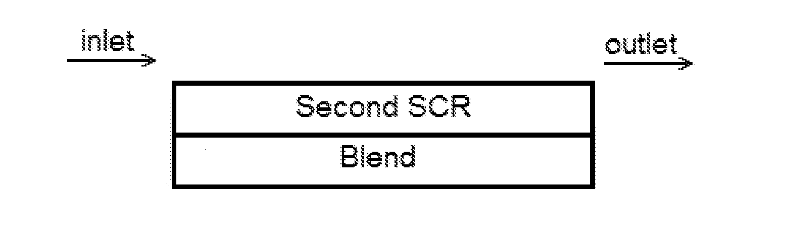
Bilayer Blend of 1 wt. % Pt on MFI Zeolite (SAR=2100) with Cu-CHA in the Bottom Layer and Cu-CHA in the Top Layer with the Full Length of the Pt Bottom Layer Covered by the Cu-CHA Top Layer

[0085]A bottom layer comprising a washcoat comprising a blend of 1 wt. % Pt on a ZSM-5 (MFI framework with SAR=2100) and a Cu-CHA (copper chabazite) was applied to a ceramic substrate. The washcoat was pulled down the substrate using a vacuum. The article was dried and calcined at about 500° C. for about 1 hour. The loading of Pt, the high SAR zeolite and the Cu-CHA on the article was 3 g / ft3, 0.18 g / in3, and 1.8 g / in3, respectively.

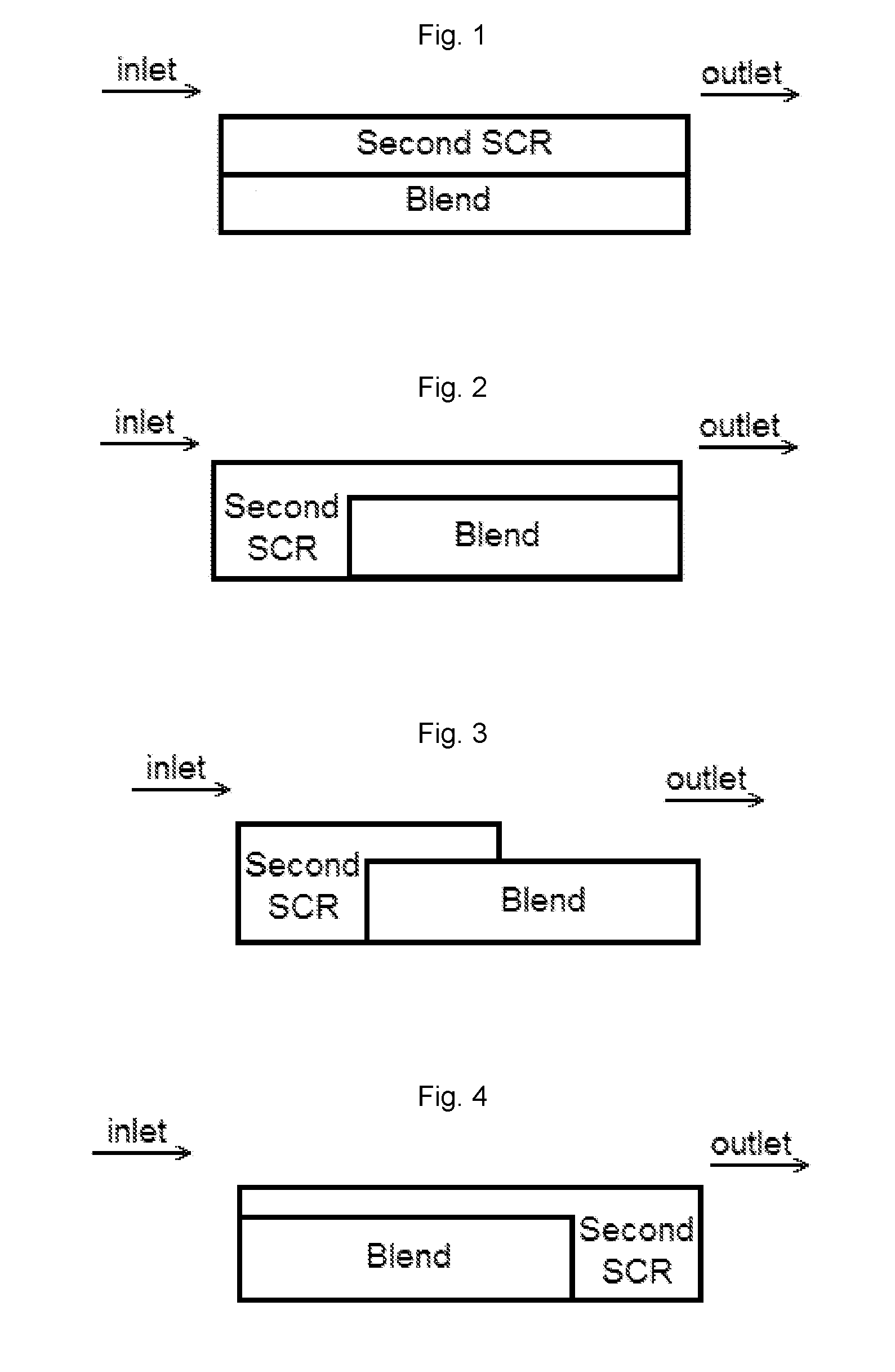
[0086]A top layer comprising a second washcoat comprising a Cu-CHA was applied to the substrate coated with the bottom layer, and then the washcoat was pulled down the substrate to a distance of about 50% of the length of the substrate using a vacuum. The article was dried and calcined at about 500° C. for about 1 hour. The loading of Cu-CHA in the top layer was 1.8 g / ...

example 2

Bilayer Blend of 2 wt. % Pt on MFI Zeolite (SAR=2100) with Cu-CHA in the Bottom Layer and Cu-CHA in the Top Layer with the Full Length of the Pt Bottom Layer Covered by the Cu-CHA Top Layer

[0087]A bottom layer comprising a washcoat comprising a blend of 2 wt. % Pt on a ZSM-5 (MFI framework with SAR=2100) and a Cu-CHA was applied to a ceramic substrate, then the washcoat was pulled down the substrate using a vacuum. The article was dried and calcined at about 500° C. for about 1 hour. The loading of Pt, the high SAR zeolite and the Cu-CHA on the article was 3 g / ft3, 0.09 g / in3, and 0.9 g / in3, respectively.

[0088]A top layer comprising a second washcoat comprising a Cu-CHA was applied to the substrate coated with the bottom layer, and then the washcoat was pulled down the substrate to a distance of about 50% of the length of the substrate using a vacuum. The article was dried and calcined at about 500° C. for about 1 hour. The loading of Cu-CHA in the top layer was 1.8 g / in3. The artic...

example 3

Bilayer Blend of 2 wt. % Pt on Amorphous Silica with Cu-CHA in the Bottom Layer and Cu-CHA in the Top Layer with the Full Length of the Pt Bottom Layer Covered by the Cu-CHA Top Layer

[0089]A bottom layer was applied to a ceramic substrate using a washcoat comprising a blend of 2 wt. % Pt on an amorphous silica and a Cu-CHA. The washcoat was applied to a ceramic substrate, and then the washcoat was pulled down the substrate using a vacuum. The article was dried and calcined at about 500° C. for about 1 hour. The loading of Pt, the high SAR zeolite and the Cu-CHA on the article was 3 g / ft3, 0.09 g / in3, and 0.9 g / in3, respectively.

[0090]A top layer was applied to the substrate coated with the bottom layer using a second washcoat comprising a Cu-CHA, and then the washcoat was pulled down the substrate to a distance of about 50% of the length of the substrate using a vacuum. The article was dried and calcined at about 500° C. for about 1 hour. The loading of Cu-CHA in the top layer was 1...


PUM

PropertyMeasurementUnit
Temperatureaaaaaaaaaa

Abstract

Catalysts having a blend of platinum on a support with low ammonia storage with an SCR catalyst are disclosed. The catalysts can also contain one or two additional SCR catalysts. The catalysts can be present in one of various configurations. Catalytic articles containing these catalysts are disclosed. The catalytic articles are useful for selective catalytic reduction (SCR) of NOx in exhaust gases and in reducing the amount of ammonia slip. Methods for producing such articles are described. Methods of using the catalytic articles in an SCR process, where the amount of ammonia slip is reduced, are also described.

Description

FIELD OF THE INVENTION[0001]The invention relates to ammonia slip catalysts (ASC), articles containing ammonia slip catalysts and methods of manufacturing and using such articles to reduce ammonia slip.BACKGROUND OF THE INVENTION[0002]Hydrocarbon combustion in diesel engines, stationary gas turbines, and other systems generates exhaust gas that must be treated to remove nitrogen oxides (NOx), which comprises NO (nitric oxide) and NO2 (nitrogen dioxide), with NO being the majority of the NOx formed. NOx is known to cause a number of health issues in people as well as causing a number of detrimental environmental effects including the formation of smog and acid rain. To mitigate both the human and environmental impact from NOx in exhaust gas, it is desirable to eliminate these undesirable components, preferably by a process that does not generate other noxious or toxic substances.[0003]Exhaust gas generated in lean-burn and diesel engines is generally oxidative. NOx needs to be reduce...

Claims


Application Information

Patent Timeline
IPC IPC(8): B01J29/76B01J29/40B01J29/80B01D53/94B01J21/04B01J21/06B01J35/00B01J23/42B01J21/08
CPCB01J29/763B01D2255/20707B01J29/40B01J29/80B01J21/08B01J21/04B01J21/063B01J35/0006B01D53/9418B01D2255/911B01D2255/9022B01D2255/9025B01D2255/50B01D2255/504B01D2255/1021B01D2255/30B01D2255/2092B01J23/42B01J37/0244B01J37/038B01J29/44B01J29/72B01J35/04B01J37/0201F01N3/2066B01J2229/186B01J2029/062F01N3/2828F01N2370/04F01N2510/063F01N2570/14F01N2570/18F01N2510/068B01D2255/1023B01D2255/1025B01D2255/1026B01D2255/1028B01D2255/104B01D2255/106B01D2255/2065B01D2255/20723B01D2255/2073B01D2255/20738B01D2255/20746B01D2255/20753B01D2255/20761B01D2255/20769B01D2255/20776B01D2255/20784Y02C20/10B01J29/723Y02A50/20B01D53/94B01J23/40B01J23/89B01J23/8926B01J29/82B01J37/02B01J29/46B01J29/76
Inventor LU, JINGFEDEYKO, JOSEPHCHEN, HAI-YINGARULRAJ, KANNESHALINGHAM
Owner JOHNSON MATTHEY PLC
Why Eureka
Try Eureka