
Light guide for low profile luminaire

a low-profile, luminaire technology, applied in lighting support devices, lighting and heating apparatus, instruments, etc., can solve the problems of less aesthetically pleasing light, poor color temperature, and high installation and operation costs of fluorescent lamps, so as to improve lighting quality, reduce manufacturing costs, and low profile

Active Publication Date: 2016-12-22
LIGHTING SCI GROUP
View PDF0 Cites 18 Cited by
  • Summary
  • Abstract
  • Description
  • Claims
  • Application Information

AI Technical Summary

Benefits of technology

The present invention is about a new type of luminaire that can be carried by a lighting fixture. It has a light source, a reflector, a light guide, and a heat sink. It is designed to fit into the space of a standard canister-type light fixture. Compared to older lamps, it gives better lighting quality while being much smaller. It also reduces the cost of manufacturing and installing a legacy lamp retrofit.

Problems solved by technology

However, fluorescent lamps are typically more expensive to install and operate than an incandescent lamp because of the requirement for a ballast to regulate the electrical current.
Many fluorescent lamps have poor color temperature, resulting in a less aesthetically pleasing light.
Also, if a fluorescent lamp that uses mercury vapor is broken, a small amount of mercury (classified as hazardous waste) can contaminate the surrounding environment.
However, a number of installation challenges and costs are associated with replacing traditional lamps with LED illumination devices.
The challenges, which are understood by those skilled in the art, include light output, thermal management, and ease of installation.
The costs, which are similarly understood by those skilled in the art, typically stem from a need to replace or reconfigure a canister fixture configured to support traditional lamps to support LEDs instead.
Consequently, employing LEDs to produce light distribution properties approximating or equaling the light dispersion properties of traditional lamps may require the costly and labor-intensive replacement or reconfiguration of the host light fixture, and / or the expensive and complexity-introducing design of LED-based solutions that minimize the installation impact to the host light fixture.
Often material and manufacturing costs are lost in this trade off.
Also, light distribution design choices such as large parabolic reflectors and multiple optics operate contrary to the objective of presenting a low profile lighting device as fully assembled.
Another challenge inherent to operating LEDs is heat.
LEDs suffer damage and decreased performance when operating in high-heat environments.
Moreover, when operating in a high-temperature ambient environment and / or a space-limited enclosure, the heat generated by an LED and its attending circuitry can cause damage to the LED.
However, heat sinks can sometimes negatively impact the light distribution properties of lighting solution, resulting in non-uniform distribution of light about the fixture.
Heat sink designs also may add to the weight and / or profile of an illumination device, thereby complicating installation, and also may limit available space for other components needed for delivering light.
Replacement of legacy lighting solutions may be complicated by the need to adapt LED-based devices to meet legacy form standards.
For example, in a commercial lighting system retrofit, disposal of a replaced lamp's fixture housing often is impractical.
Also, power supply requirements of LED-based lighting systems can complicate installation of LEDs as a retrofit to existing light fixtures.
Too little current and voltage may result in little or no light.
Too much current and voltage can damage the light-emitting junction of the LED.
However, employing legacy lamp technology may result in a design that suffers light losses (both to reflection and to absorption).
However, sandwiching a light-confining interface layer between multiple light guides operates contrary to the objectives of constructing a low profile luminaire and minimizing design and manufacturing complexity.
However, because the majority of light injected into the edge of the light guide originates from directional-light generating LEDs, a complex plurality of display elements must be designed into the light guide to shape light propagating through the light guide into a substantially uniform illumination profile.

Method used


Image

  • Light guide for low profile luminaire
  • Light guide for low profile luminaire
  • Light guide for low profile luminaire

Examples


Embodiment Construction

[0041]The present invention will now be described more fully hereinafter with reference to the accompanying drawings, in which preferred embodiments of the invention are shown. This invention may, however, be embodied in many different forms and should not be construed as limited to the embodiments set forth herein. Rather, these embodiments are provided so that this disclosure will be thorough and complete, and will fully convey the scope of the invention to those skilled in the art. Those of ordinary skill in the art realize that the following descriptions of the embodiments of the present invention are illustrative and are not intended to be limiting in any way. Other embodiments of the present invention will readily suggest themselves to such skilled persons having the benefit of this disclosure. Like numbers refer to like elements throughout.

[0042]Although the following detailed description contains many specifics for the purposes of illustration, anyone of ordinary skill in th...


PUM


Abstract

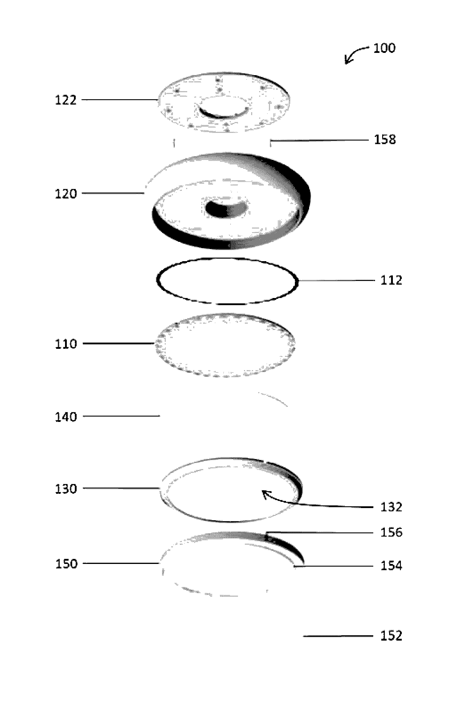
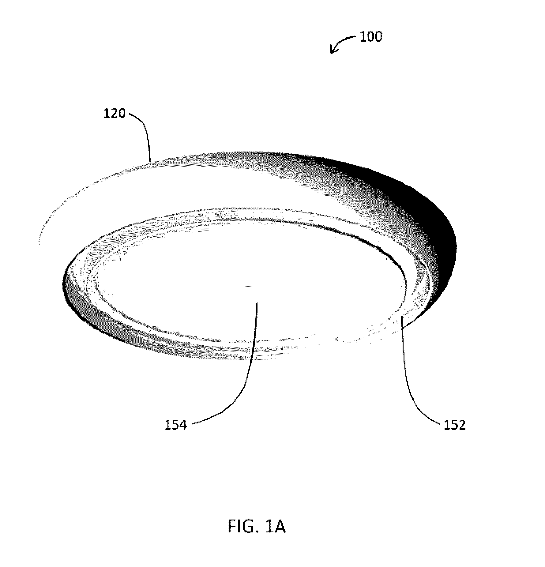
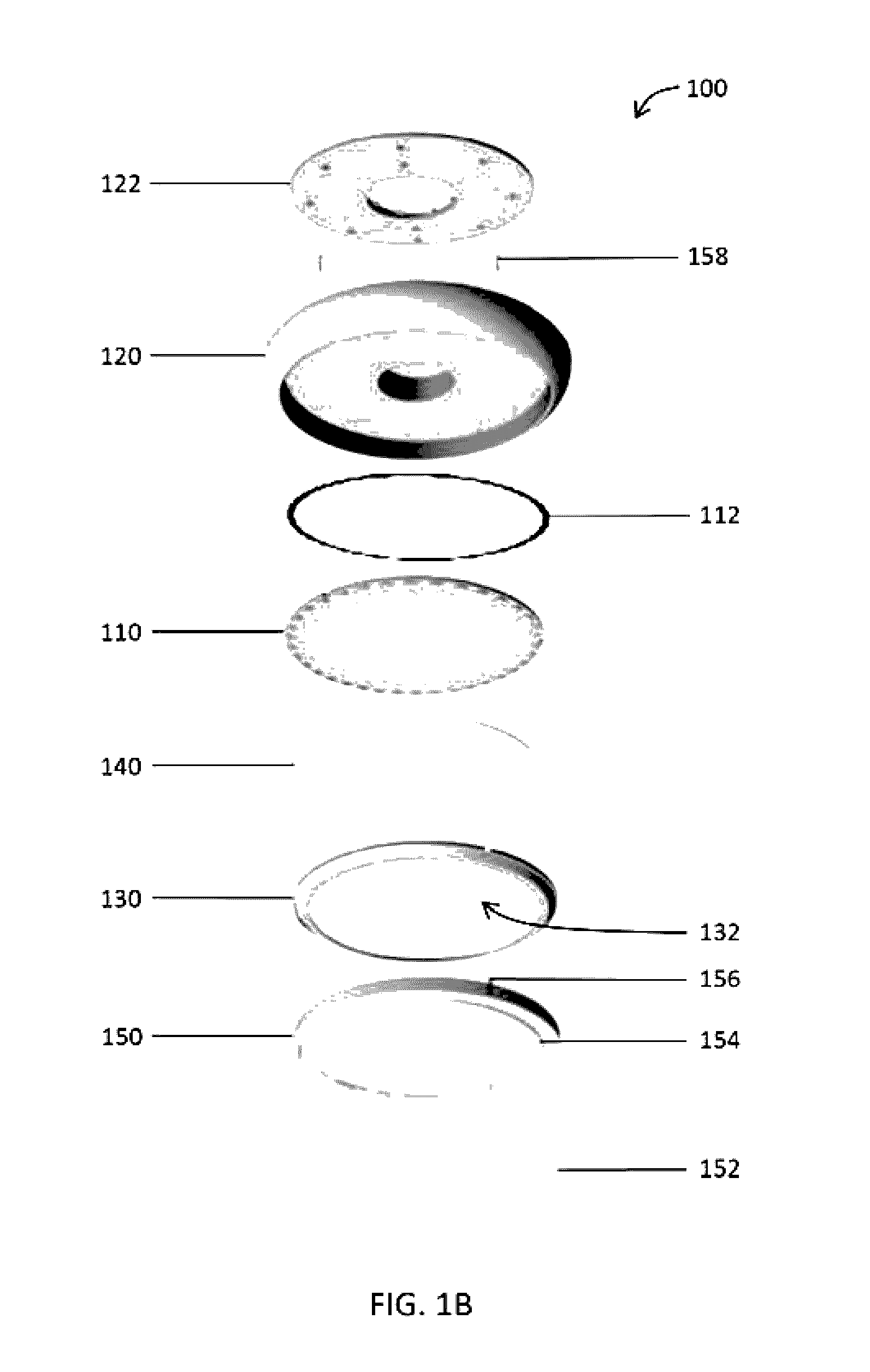
A luminaire comprising a heat sink, a light source to emit a source light, a heat spreader having inner and outer surfaces, and LEDs carried by a circuit board and disposed generally along a periphery of the inner surface and positioned in thermal communication therewith. The luminaire comprises a reflector disposed coextensively with the LEDs and comprising an aperture. An outer edge of the aperture defines an inner rim of the reflector. A light guide positioned between the reflector and the light source exhibits a height defined as the distance between the inner surface of the heat spreader and a plane defined by the inner rim of the reflector. The light guide comprises deformations and / or lens portions configured to change the source light into a shaped light that is directed through the aperture. The deformations are characterized by a common shape positioned about a center of the light guide.

Description

RELATED APPLICATIONS[0001]This application is a continuation-in-part and claims the benefit under 35 U.S.C. §120 of U.S. patent application Ser. No. 14 / 863,150 (Attorney Docket No. 221.00270) titled Low Profile Luminaire And Associated Systems And Methods filed Sep. 23, 2015, which is, in turn, a continuation of U.S. patent application Ser. No. 14 / 014,512 (Attorney Docket No. 221.00147), now U.S. Pat. No. 9,157,581 titled Low Profile Luminaire With Light Guide And Associated Methods filed Aug. 30, 2013, which is, in turn, a continuation-in-part of U.S. patent application Ser. No. 13 / 476,388 (Attorney Docket No. 221.00381), now U.S. Pat. No. 8,672,518 titled Low Profile Light and Accessory Kit For The Same filed May 21, 2012, which is, in turn, a continuation-in-part of U.S. patent application Ser. No. 12 / 775,310 (Attorney Docket No. 221.00337), now U.S. Pat. No. 8,201,968 titled Low Profile Light filed May 6, 2010, which claims the benefit of U.S. Provisional Patent Application Ser....

Claims


Application Information

Patent Timeline
Patent Type & Authority Applications(United States)
IPC IPC(8): F21V8/00F21K9/61F21K9/23F21V29/70
CPCG02B6/0073G02B6/0031F21V29/70F21K9/23G02B6/0085F21K9/61G02B6/0041F21S8/026F21V21/20F21V23/0471F21Y2101/00F21Y2105/00F21V29/83F21V29/85F21K9/20F21K9/68F21Y2103/33F21Y2105/10F21Y2115/10G02B6/0035G02B6/0065G02B6/0068F21V23/02F21V2200/20G02B6/00
Inventor BOOMGAARDEN, MARK PENLEYROMEU, RICARDOKELLEY, RYANHOLLAND, ERIC
Owner LIGHTING SCI GROUP
Learn More