Power Conversion Unit, Power Converter, and Power Conversion Method
a power conversion unit and converter technology, applied in the field of circuits for converting power, can solve problems such as current flowing through parallel connected power semiconductor elements, and achieve the effect of reducing the imbalance of control signals
- Summary
- Abstract
- Description
- Claims
- Application Information
AI Technical Summary
Benefits of technology
Problems solved by technology
Method used
Image


Examples
example 1
[0022]A UPS (Uninterruptible Power-supply System) will be described as an example.
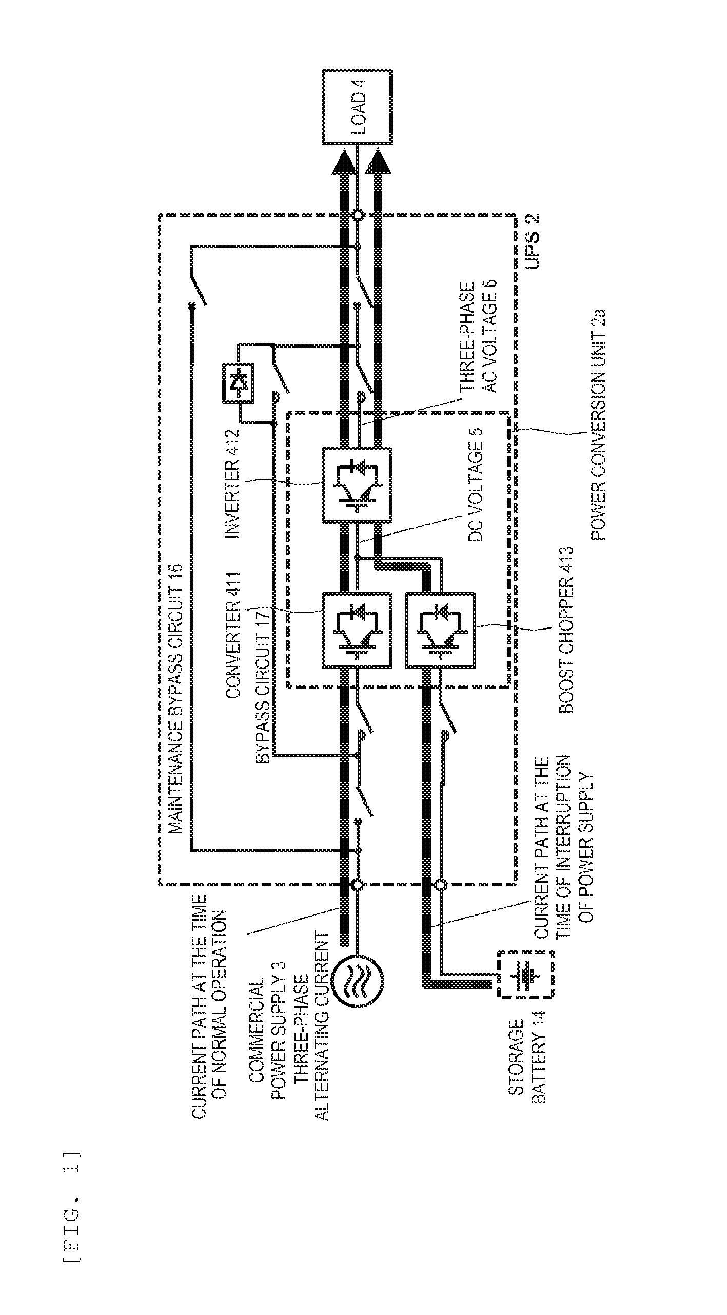
[0023]FIG. 1 is a circuit diagram of a UPS according to an example.
[0024]This UPS 2 is an online type UPS that can uninterruptedly continue power supply at the time of interruption of power supply. Note that the invention is not limited to the online type UPS and may also be another type UPS such as an off line type UPS.
[0025]A commercial power supply 3 having a three-phase alternating current supplies power to a load 4 via an converter 411 and an inverter 412 at the time of normal operation. Herein, the converter 411 converts the commercial power supply 3 having a three-phase alternating current into a DC voltage 5 and supplies the DC voltage 5 to the inverter 412. The inverter 412 converts the DC voltage 5 into a three-phase AC power 6. With this, even in the case where a change in voltage such as instantaneous voltage drop occurs in the commercial power supply 3, power that is equal to that of a nor...
example 2
[0069]FIG. 10 is a perspective diagram of a power conversion unit 300b in Example 2.
[0070]As compared with Example 1, the power conversion unit 300b in this example includes a heat receiving portion 130b instead of the heat receiving portion 130, includes a heat pipe 140b instead of the heat pipe 140, and includes a radiator fin 150b instead of the radiator fin 150. The heat pipe 140b passes through the heat receiving portion 130b and is protruded from the heat receiving portion 130b in a direction between a −Y direction and a Z direction. The radiator fin 150b is connected to a portion of the heat pipe 140b, the portion being protruded from the heat receiving portion 130b. In this example, for example, a fan is provided in the −Z direction of the radiator fin 150b and cools the radiator fin 150b by sending air in the Z direction.
[0071]FIG. 11 is a perspective diagram of a power conversion part 2a in Example 2.
[0072]The power conversion part 2a in this example includes a plurality o...
PUM
 Abstract
Description
Claims
Application Information