Golf Club Head With Adjustable Center of Gravity
a golf club and center of gravity technology, applied in the field of golf club heads, can solve the problems of not optimizing weight adjustment, achieve the effect of maximizing aesthetic appearance, facilitating movement and fixing weights, and preserving the function of movable weights
- Summary
- Abstract
- Description
- Claims
- Application Information
AI Technical Summary
Benefits of technology
Problems solved by technology
Method used
Image
Examples
first embodiment
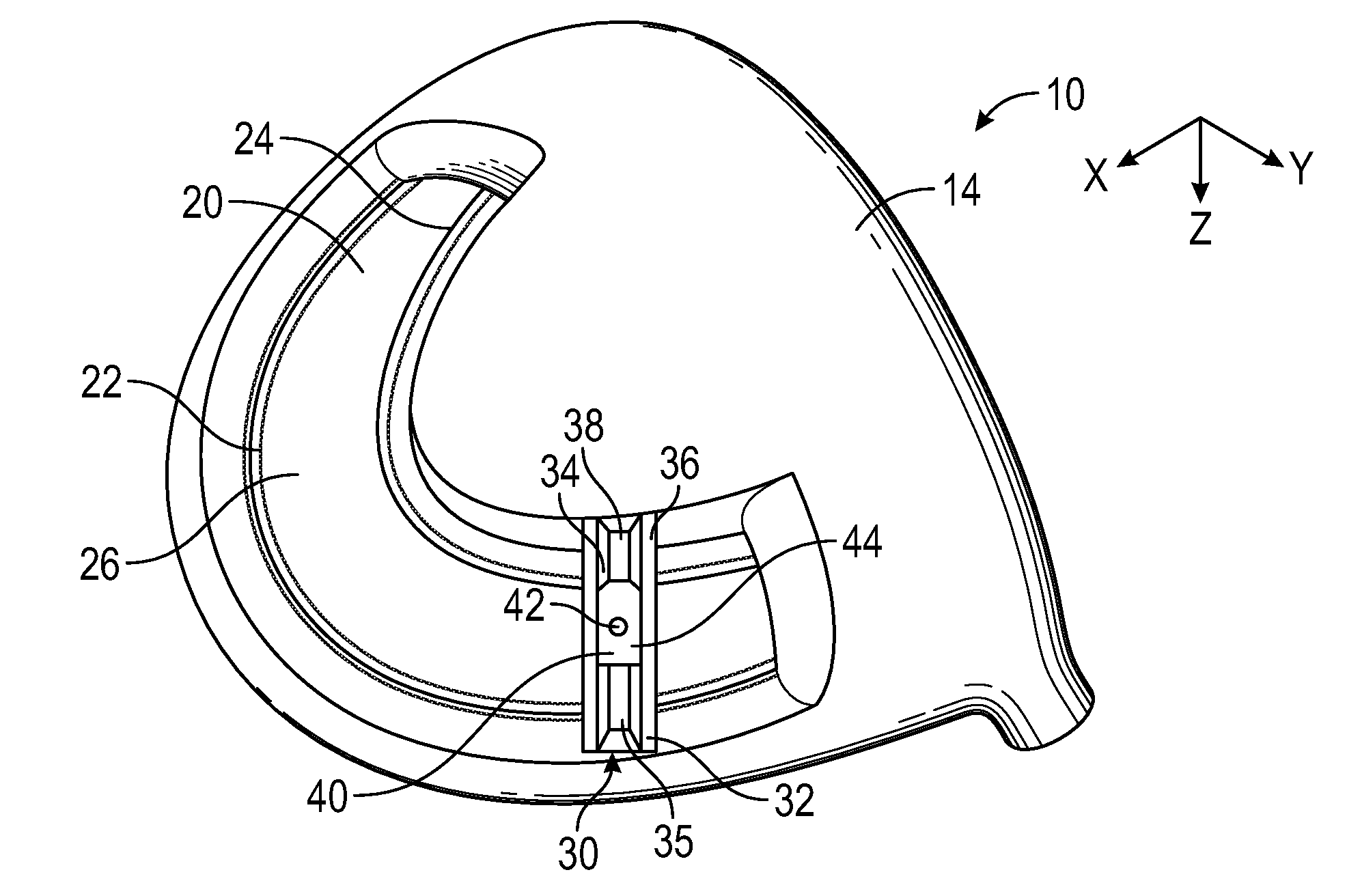
[0027]the present invention is shown in FIG. 1. The golf club head 10 comprises a channel 20 disposed within the sole 14 of the golf club head, though in alternative embodiments the channel 20 may be disposed in a ribbon or skirt portion or in the crown 12 of the golf club head 10. The channel 20 extends from a heel side 16 of the club head proximate a hosel 11 to a toe side 18 of the golf club head 10 along the rear edge of the sole 14, and has a pair of rails 22, 24 extending upwards from the floor 26 of the channel. A slidable, two-piece cartridge 30 is disposed within the channel 20. The cartridge 30 includes an upper portion 32 with a slot 35 sized to receive a slidable weight 40 and a pair of rails 34, 36 extending from a floor 38 of the slot 35, a nutplate (not shown), and a bolt connecting the upper portion 32 to the nutplate. The upper portion 32 and the nutplate are disposed on either sides of the rails 22, 24, and grip the rails 22, 24 between them when the bolt is tighte...
third embodiment
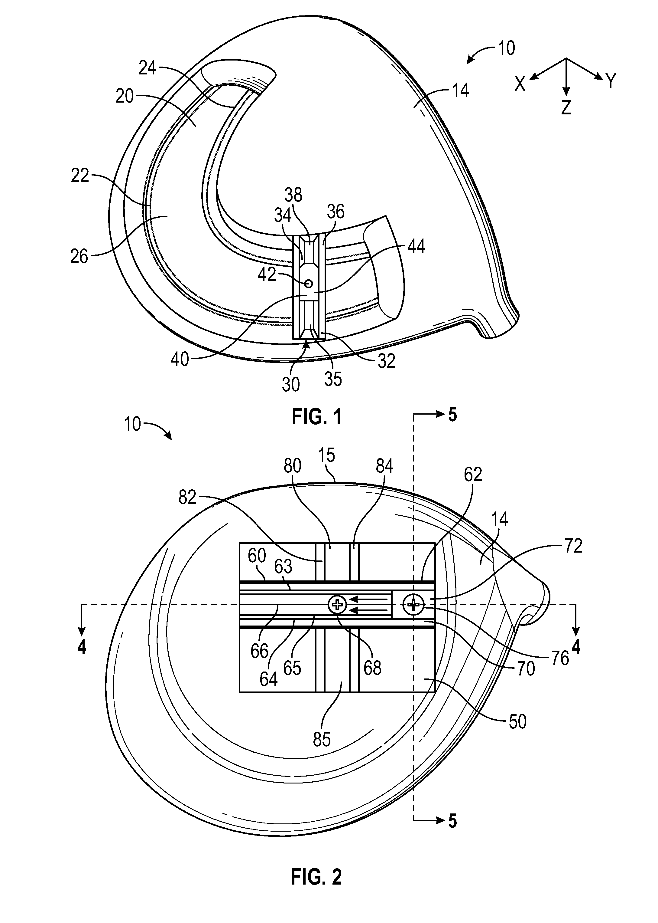
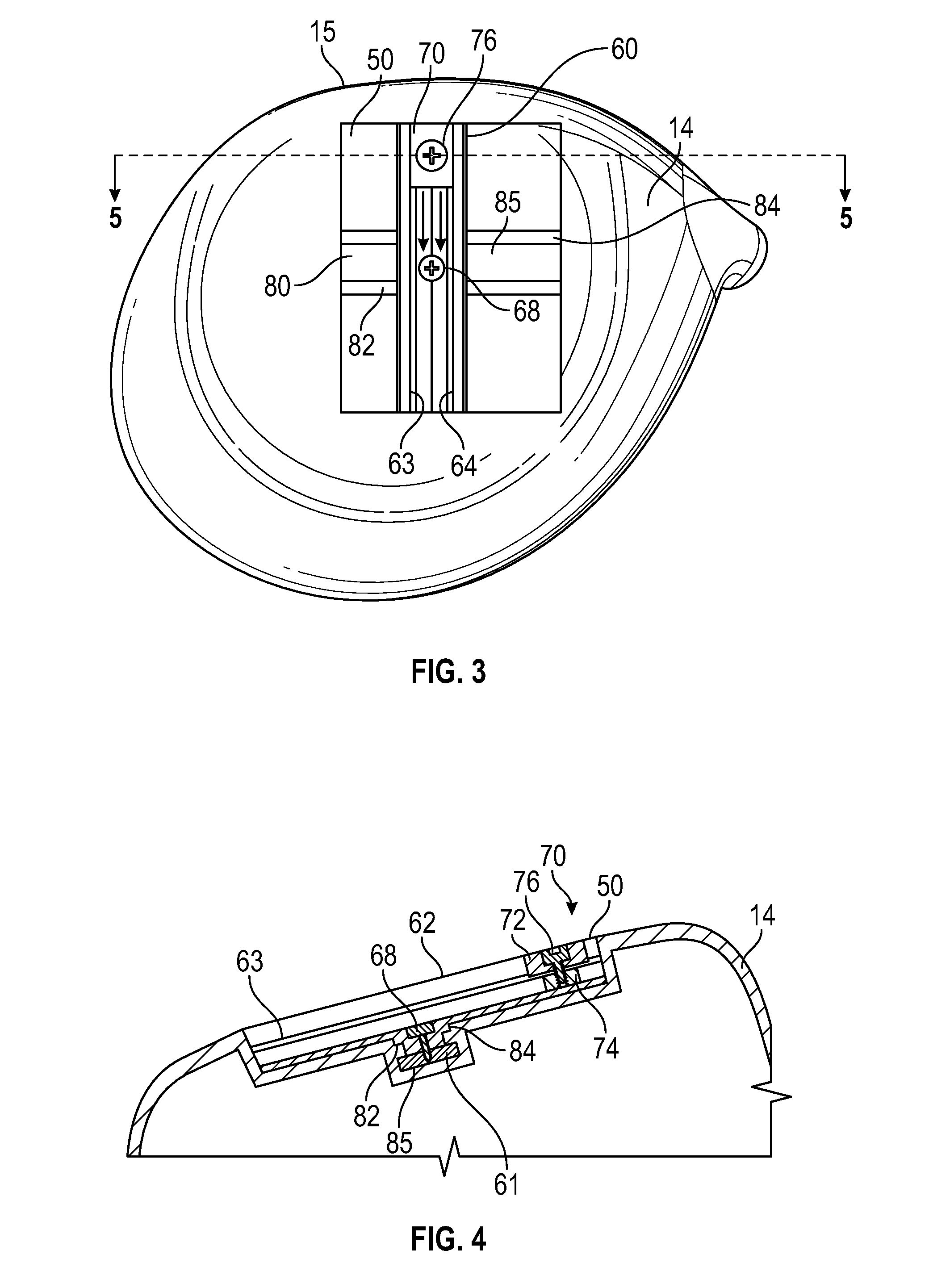
[0030]A fourth, preferred embodiment is shown in FIGS. 6-11. In this embodiment, the golf club head 10 comprises all of the same features as the third embodiment, except that the channel 100 is further recessed into the floor 55 of the rectangular recessed area 50 and comprises a pair of opposing vertical sidewalls 102, 104 from which a pair of rails 103, 105 extend parallel to the floor 106 of the channel 100. The channel 100 is sized to receive the base portion 115 of the elongated weight receptacle 110, which fits between the floor 106 and the rails 103, 105 as shown in FIG. 8. The base portion 115 has a threaded through-bore 116 sized to receive the threaded portion of a bolt 68, and the threaded through-bore 116 aligns with a through bore 113 in a recessed, bolt-receiving portion 114 of the upper portion 112 of the elongated weight receptacle 110. When the bolt 68 is tightened, the base portion 115 and the upper portion 112 clamp onto the rails 103, 105. This configuration allo...
PUM
 Abstract
Description
Claims
Application Information
 - R&D
- Intellectual Property
- Life Sciences
- Materials
- Tech Scout
- Unparalleled Data Quality
- Higher Quality Content
- 60% Fewer Hallucinations
Browse by: Latest US Patents, China's latest patents, Technical Efficacy Thesaurus, Application Domain, Technology Topic, Popular Technical Reports.
© 2025 PatSnap. All rights reserved.Legal|Privacy policy|Modern Slavery Act Transparency Statement|Sitemap|About US| Contact US: help@patsnap.com


