Pressure limiters

a technology of limiters and valves, applied in the field of valves, can solve problems such as weight and packaging penalties, and achieve the effects of preventing leakage, preventing fluid buildup, and reducing the force of springs

Inactive Publication Date: 2016-12-29
HAMILTON SUNDSTRAND CORP
View PDF3 Cites 9 Cited by
  • Summary
  • Abstract
  • Description
  • Claims
  • Application Information

AI Technical Summary

Benefits of technology

[0008]The pressure control mechanism can include a control pressure outlet in selective fluid communication with the flow path and a ball valve defined between the control pressure outlet and the flow path. In a closed position the ball valve can seal the flow path to block fluid flow from the system inlet to the system outlet while allowing fluid flow from the control pressure outlet to the system outlet. In an open position, the ball valve can allow fluid flow from the system inlet to the system outlet while blocking fluid flow from the control pressure outlet to the system outlet.
[0009]The pressure limiter can include a valve body defining an inlet chamber in fluid communication with the system inlet, an outlet chamber downstream from the inlet chamber, and a bleed orifice defined in the outlet chamber to hinder fluid buildup in the flow path downstream from the outlet chamber. A poppet is defined in the flow path between the inlet chamber and the outlet chamber. The poppet can seal against the valve body in a closed position to block fluid flow in the flow path between the inlet chamber and the outlet chamber. In an open position, the poppet can be separated from the valve body to allow fluid flow from the inlet chamber to the outlet chamber.
[0010]The valve body can include a spring chamber opposite of the inlet chamber. The spring chamber can include a spring having a seat. The seat can be operatively connected to a guide of the poppet. The seat of the spring can inhibit leakage from the flow path to the spring chamber when the poppet is in an open position. The valve body can be a first valve body and the outlet chamber can be in fluid communication with an inlet of a second valve body of the pressure limiter, e.g. a back-up valve body. The second valve body of the pressure limiter can be configured to close at a higher pressure than that of the first valve body. A spring of the second valve body can have a higher spring force than a spring of the first valve body.
[0011]A pressure limiter includes a valve body defining an inlet chamber, an outlet chamber in selective fluid communication with a flow path defined from the inlet chamber to the outlet chamber, and a bleed orifice defined in the outlet chamber to hinder fluid buildup in the outlet chamber. A poppet is defined in the flow path between the inlet chamber and the outlet chamber. The poppet seals against the valve body in a closed position to block fluid flow in the flow path between the inlet chamber and the outlet chamber to prevent fluid flow from reaching a downstream pressure control mechanism when the pressure of the fluid entering the inlet chamber exceeds a maximum threshold. When the pressure of the fluid entering the inlet chamber is below the maximum threshold the poppet is separated from the valve body in an open position to allow fluid flow from the inlet chamber to the outlet chamber.

Problems solved by technology

Typically, this results in weight and packaging penalties due to the larger coils and spring forces required, even though the device may not be required to operate at higher pressures.

Method used


Image

  • Pressure limiters
  • Pressure limiters
  • Pressure limiters

Examples


Embodiment Construction

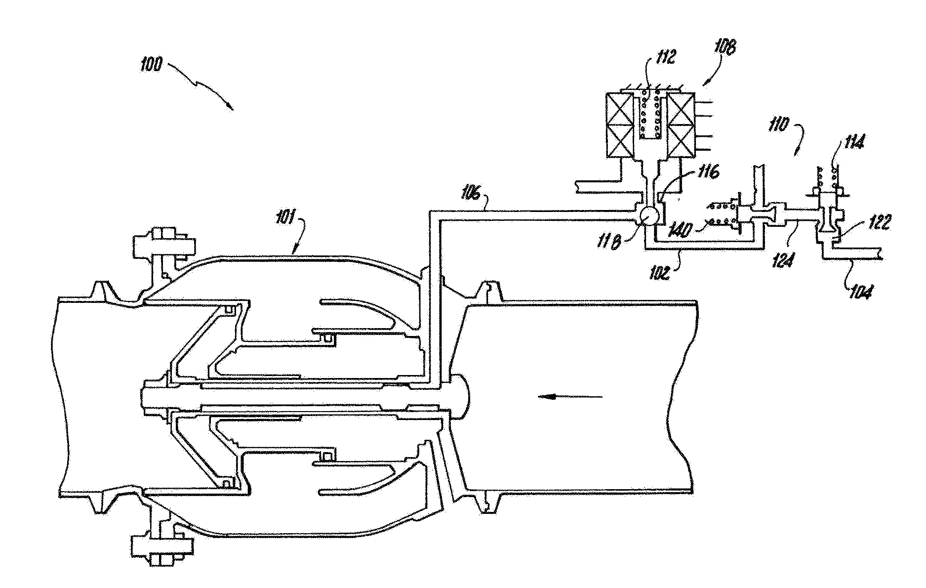
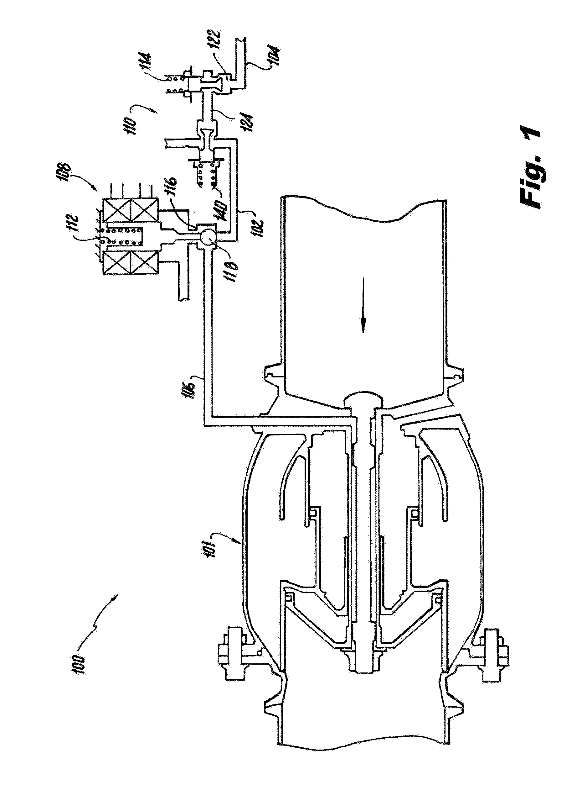
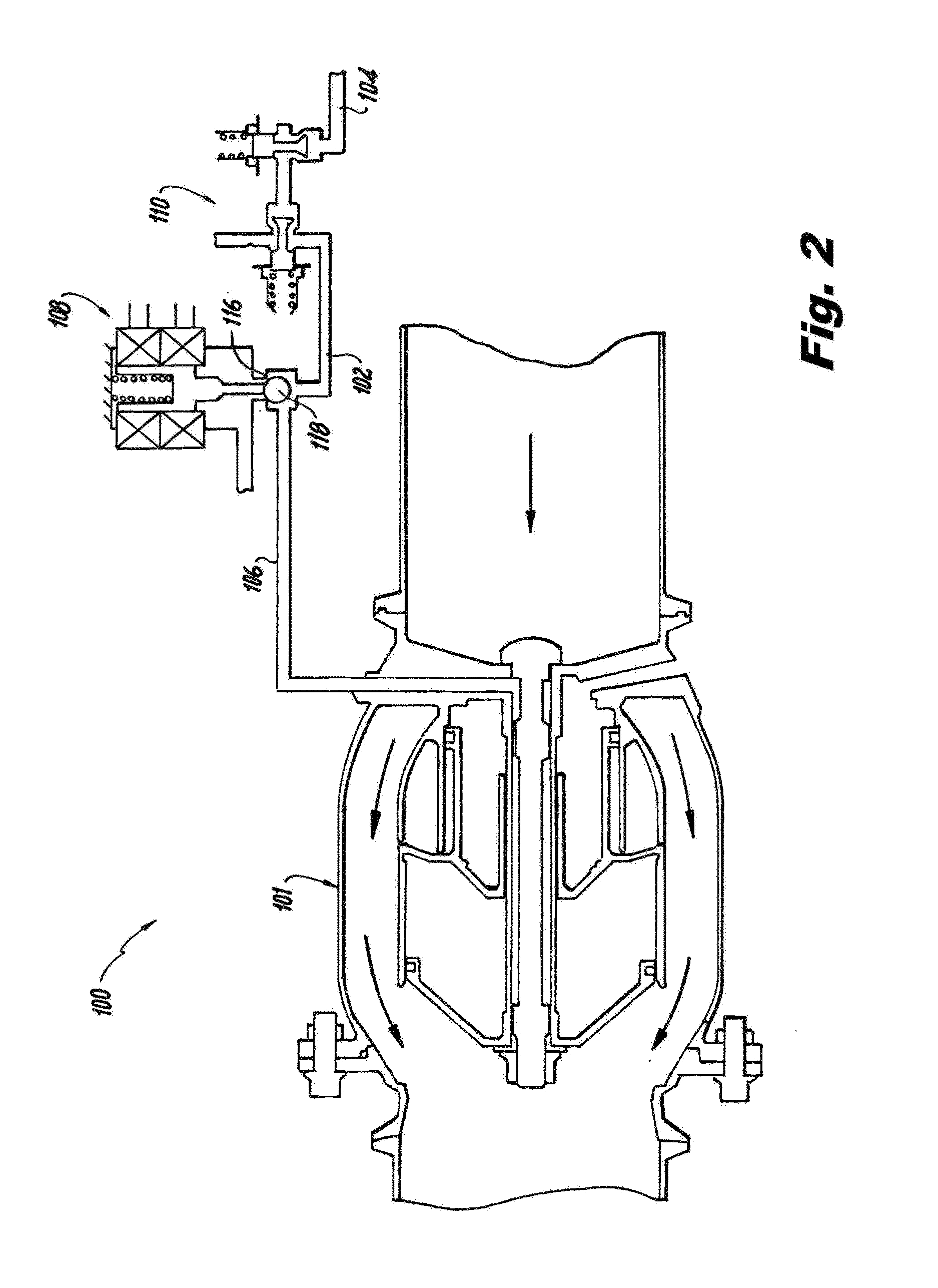
[0017]Reference will now be made to the drawings wherein like reference numerals identify similar structural features or aspects of the subject disclosure. For purposes of explanation and illustration, and not limitation, a partial view of an exemplary embodiment of a bleed valve system constructed in accordance with the disclosure is shown in FIG. 1 and is designated generally by reference character 100. Other embodiments of bleed valve systems in accordance with this disclosure, or aspects thereof, are provided in FIGS. 2 and 3, as will be described. Bleed valve system 100 is smaller and lighter than traditional systems, resulting in reduced heat and energy consumption.

[0018]As shown in FIG. 1, a bleed valve system 100 includes a flow path 102 defined between a system inlet 104 and a system outlet 106. A pressure control mechanism 108 is defined in flow path 102 downstream from system inlet 104 to selectively block fluid flow in flow path 102. A pressure limiter 110 is defined in ...


PUM


Abstract

A bleed valve system includes a flow path defined between a system inlet and a system outlet. A pressure control mechanism is defined in the flow path downstream from the system inlet to selectively block fluid flow in the flow path. A pressure limiter is defined in the flow path downstream from the system inlet and upstream from the pressure control mechanism to block the flow path when the pressure at the system inlet is greater than the pressure capacity of the pressure control mechanism.

Description

BACKGROUND OF THE INVENTION[0001]1. Field of the Invention[0002]The present disclosure relates to valves, and more particularly to pressure control mechanisms for valves used in bleed systems such as those used in gas turbine engines.[0003]2. Description of Related Art[0004]A variety of devices require a substantially constant supply of pressurized fluid in order to function properly. For example, secondary aircraft systems such as environmental control or anti-ice systems often require an input supply of constant pressure gas. Sources of pressurized gas, for example, are present in the compressor of gas turbine engine. If the pressure in one of the sources, e.g. an intermediate-pressure (IP) bleed valve, is too low for the secondary aircraft system, high-pressure bleed fluid from a high-pressure (HP) bleed valve is utilized. To transition from the IP bleed fluid to the HP bleed fluid, a pressure control mechanism, e.g. an electromechanical interface such as a solenoid, is actuated ...

Claims


Application Information

Patent Timeline
Patent Type & Authority Applications(United States)
IPC IPC(8): F01D17/14F16K15/02F01D17/10F16K11/087
CPCF01D17/145F16K11/087F05D2260/606F01D17/105F05D2220/32F16K15/025B64D2013/0618F02C6/08F04D27/0215F04D27/0223F04D27/023F04D27/0292F05D2270/301F05D2270/65Y02T50/50Y02T50/60
Inventor MAROCCHINI, FRANCIS P.GOODMAN, ROBERTRICKIS, AARON F.MCBRIEN, GARY M.
Owner HAMILTON SUNDSTRAND CORP
Why Eureka
Try Eureka