Heat exchanger

Active Publication Date: 2016-12-29
KYUNGDONG NAVIEN
View PDF3 Cites 7 Cited by
  • Summary
  • Abstract
  • Description
  • Claims
  • Application Information

AI Technical Summary

Benefits of technology

The present invention provides a heat exchanger that can reduce the number of components, simplify the coupling structure, and improve thermal efficiency. It achieves this by integrating a sensible heat exchanger and a latent heat exchanger, and also integrating a heating medium passage, a combustion gas passage, and an outer wall structure sealing outer lateral surfaces of the heating medium passage and the combustion gas passage. The heat exchanger has a long flow channel for the heating medium and combustion gas, which maximizes thermal efficiency by promoting generation of a turbulent flow. Additionally, the heat exchanger collects combustion heat of the combustion gas into the heating medium, improving thermal efficiency.

Problems solved by technology

However, such a heat exchanger of a condensing type has a problem in that a dimension of the heat exchanger should be increased due to the structure in which the air blower is located at the upper part of the housing and the sensible heat exchanger and the latent heat exchanger are longitudinally located inside the housing.
However, the heat exchanger disclosed in the prior art documents has a disadvantage in which a torsional phenomenon occurs while the heat exchange pipe is helically processed to cause a difficulty in processing an entire surface of the heat exchange pipe in a uniform shape.
Also, when a heat exchange pipe has undergone a bending process, damage may occur upon the bending process due to a difference of a strain rate between an inside surface of the heat exchange pipe toward a center of a burner and an outside surface thereof opposite the inside surface, and thus the heat exchange pipe exchanging heat with combustion gas may have a limitation to be formed in a wider width.
As a result, there is a structural limitation in which a sufficient area for processing a irregular shape promoting a turbulent flow on a surface of a heat exchange pipe is not secured as a configuration for more improving heat transfer efficiency between a heating medium and combustion gas.
In addition, the conventional heat exchanger has problems in that an installation structure of the heat exchanger is complicated because a housing H is separately provided as a configuration for tightly sealing an outer circumference of the heat exchange pipe 20 being helically wound, and a heat source of combustion gas is not fully transferred to a heating medium flowing inside the heat exchange pipe 20 because heat transferred to the housing H is directly radiated and dissipated to an outside thereof, wherein the heat is transferred to the housing H while the combustion gas generated by combustion of the burner 10 passes a longitudinally separated space of the heat exchange pipe 20 to flow through a space between the heat exchange pipe 20 and an inner wall of the housing H.

Method used


Image

  • Heat exchanger
  • Heat exchanger
  • Heat exchanger

Examples


Embodiment Construction

[0056]Hereinafter, a configuration and an action with respect to a preferred embodiment of the present disclosure will be described in detail as follows with reference to the accompanying drawings.

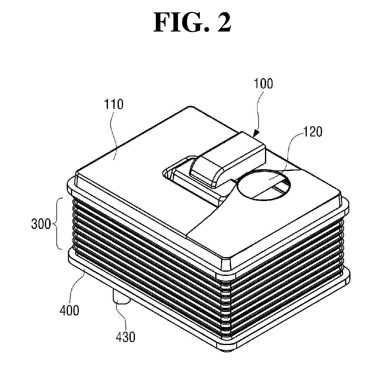
[0057]With reference to FIGS. 2 to 5, a heat exchanger according to the present disclosure includes an upper duct 100 at which a mixture inflow unit 110 and a flue 120 are formed, wherein a mixture of air and fuel flows in the mixture inflow unit 110 and the flue 120 discharges combustion gas; a burner 200 for burning the mixture flowing therein through the mixture inflow unit 110; a heat exchange unit 300 provided at a circumference of the burner 200 to exchange heat between combustion gas generated by combustion of the burner 200 and a heating medium and configured with a plurality of unit plates 310, 320, 330, 340, 350, 360, 370, 380, 390, and 390-1 which are longitudinally stacked; and a lower duct 400 coupled to a lower part of the heat exchange unit 300.

[0058]The mixture inflow unit ...


PUM


Abstract

The present invention relates to a heat exchanger comprising: a burner for combusting a mixture of air and fuel; and a heat exchange unit in which heat is exchanged between combustion gas caused by the combustion of the burner and a heating medium, wherein the heat exchange unit includes a plurality of unit plates stacked on each other, and a sensible-heat exchange unit and a latent-heat exchange unit coaxially disposed around the burner are integrally formed with the unit plates.

Description

CROSS-REFERENCE TO RELATED APPLICATIONS[0001]This application is a continuation application of International Application No. PCT / KR2015 / 002456 filed on Mar. 13, 2015, which claims priority to Korean Application No. 10-2014-0031442 filed on Mar. 18, 2014. The applications are incorporated herein by reference.TECHNICAL FIELD[0002]The present disclosure relates to a heat exchanger provided in a boiler for heating or hot water, and more particularly, to a heat exchanger having a simplified structure and also improving heat transfer efficiency between a heating medium and combustion gas by stacking a unit plate manufactured in a constant pattern to integrally form a sensible-heat exchange unit and a latent-heat exchange unit which are arranged at the circumference of a burner in a coaxial structure.BACKGROUND ART[0003]A boiler for heating or hot water is a device for applying heat to heating water or direct water (hereinafter, referred to as a ‘heating medium’) by a heat source to heat a...

Claims


Application Information

Patent Timeline
IPC IPC(8): F24H1/16F24H8/00F24H1/30
CPCF24H1/165F24H8/00F24H1/30F24H1/38F28F3/044F28D9/0012F28D9/0043F28D2021/0024Y02B30/00
Inventor KIM, YOUNG MO
Owner KYUNGDONG NAVIEN
Why Eureka
Try Eureka