Protective membrane structure and method of removing membrane

Inactive Publication Date: 2016-12-29
INTERFACE OPTOELECTRONICS SHENZHEN +1
View PDF2 Cites 0 Cited by
  • Summary
  • Abstract
  • Description
  • Claims
  • Application Information

AI Technical Summary

Benefits of technology

The patent is about a protective membrane structure and a method for removing it. The structure is designed to make it easier for workers to hold and remove the main body of a device. This is achieved by creating creasing lines on the surface of the pulling member, which pushes away from the main body. The arrangement and location of the creasing lines can also be adjusted to adjust the warping of the pulling member. Overall, this makes the removal process easier and more efficient.

Problems solved by technology

In this regard, it becomes more difficult for the assembly workers to remove the protective membranes by the pulling taps due to the close attachment of the pulling taps and the protective membranes.

Method used


Image

  • Protective membrane structure and method of removing membrane
  • Protective membrane structure and method of removing membrane
  • Protective membrane structure and method of removing membrane

Examples


Embodiment Construction

[0031]Reference will now be made in detail to the present embodiments of the disclosure, examples of which are illustrated in the accompanying drawings. Wherever possible, the same reference numbers are used in the drawings and the description to refer to the same or like parts.

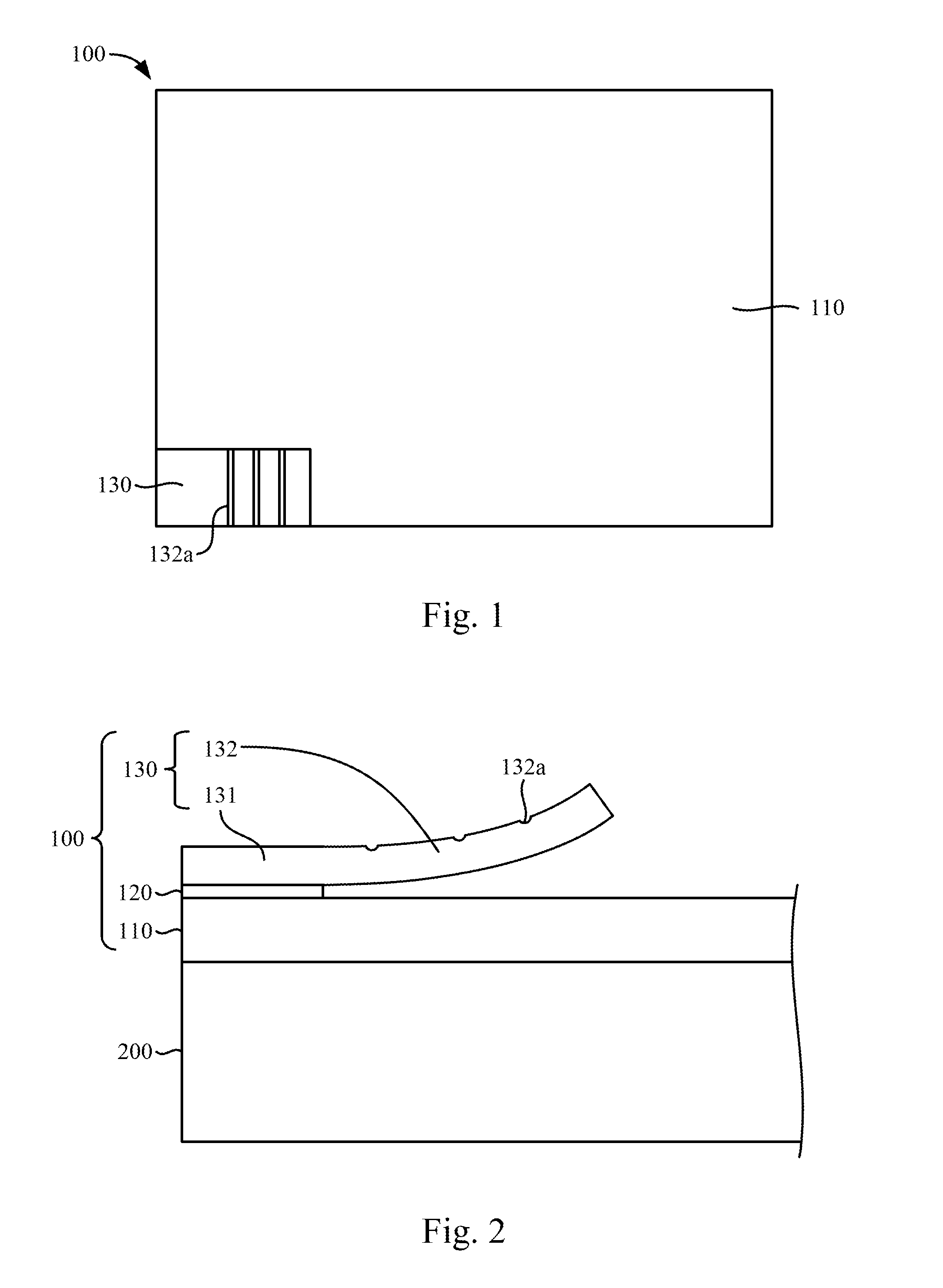
[0032]FIG. 1 is a top view of a protective membrane structure 100 according to an embodiment of the disclosure. FIG. 2 is a side view illustrating a protective membrane structure 100 disposed on a panel module 200 according to an embodiment of the disclosure.

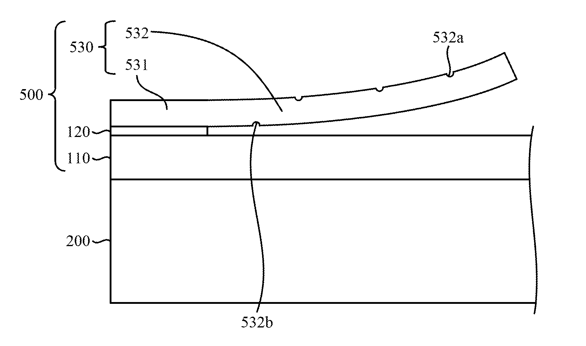
[0033]As shown in FIG. 1 and FIG. 2, in the embodiment, the protective membrane structure 100 is configured to protect the panel module 200. The protective membrane structure 100 includes a main body 110, an adhesive member 120, and a pulling member 130. The main body 110 is attached to the panel module 200. The adhesive member 120 is disposed on the main body 110. The pulling member 130 is located over the main body 110 and has an adhesive portion 131 an...


PUM

PropertyMeasurementUnit
Adhesivityaaaaaaaaaa

Abstract

A protective membrane structure is configured to protect a pan& module. The protective membrane structure includes a main body, an adhesive member, and a pulling member. The main body is attached to the panel module. The adhesive member is disposed on the main body. The pulling member is located over the main body and has an adhesive portion and a warping portion connected to each other. The adhesive member is adhered between the main body and the adhesive portion. The warping portion warps away from the main body.

Description

RELATED APPLICATIONS[0001]This application claims priority to Chinese Application Serial Number 201510357953.8, filed Jun. 25, 2015, which is herein incorporated by reference.BACKGROUND[0002]Technical Field[0003]The present disclosure relates to a protective membrane structure and a method of removing membrane, and more particularly, to a protective membrane structure for protecting a panel module and a method of removing membrane.[0004]Description of Related Art[0005]For conventional display panel modules and / or touch panel modules, protective membranes are generally attached onto the display panel modules and / or touch panel modules to avoid damages from transportation or testing processes. The protective membranes are removed from the display panel modules and / or touch panel modules when assembling processes begin. For example, the protective membranes are adhered to pulling taps by adhesive members. While removing the protective membranes, assembly workers pull the pulling taps t...

Claims


Application Information

Patent Timeline
IPC IPC(8): G06F3/041B32B43/00
CPCG06F3/0412G06F2203/04103G06F2203/04107B32B43/006B65B33/02B65B61/22B65B69/00G06F3/041
Inventor JEN, CHEN-MINGTSAI, CHENG-FENG
Owner INTERFACE OPTOELECTRONICS SHENZHEN
Why Eureka
Try Eureka