

Piezoelectric device, liquid ejection head, and liquid ejection apparatus
- Summary
- Abstract
- Description
- Claims
- Application Information
AI Technical Summary
Benefits of technology
Problems solved by technology
Method used
Image

Examples
Embodiment Construction
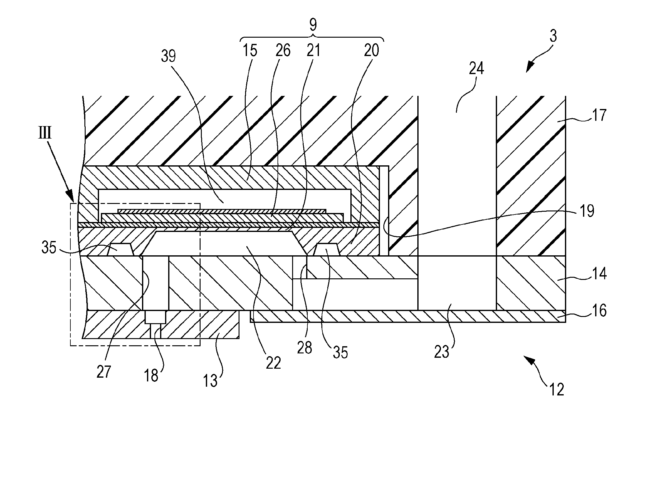
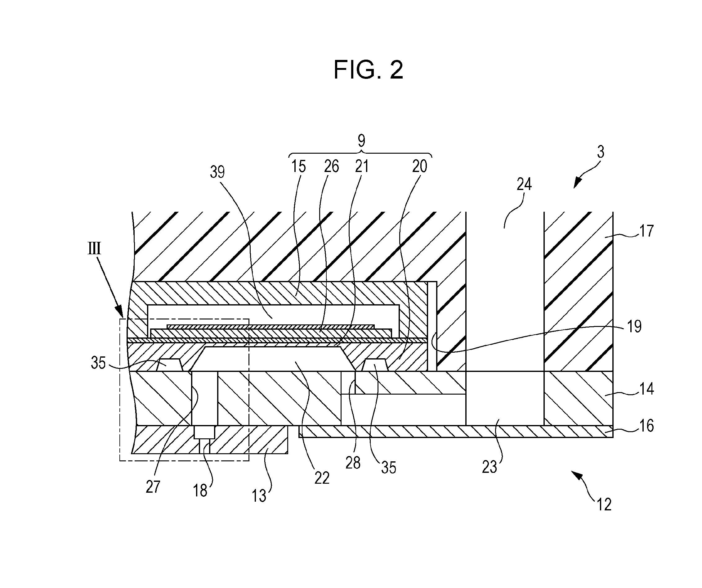
[0032]The following describes the embodiments of the invention with reference to the accompanying drawings. It should be noted that in the following embodiments, various features are described as preferable specific examples of the invention. However, the invention is not limited to these examples, unless so stated. As an example, the following describes an ink jet printer (hereinafter referred to as a printer) that is a type of liquid ejection apparatus including an ink jet recording head (hereinafter referred to as a recording head) that is a type of liquid ejection head including a piezoelectric device according to the invention.
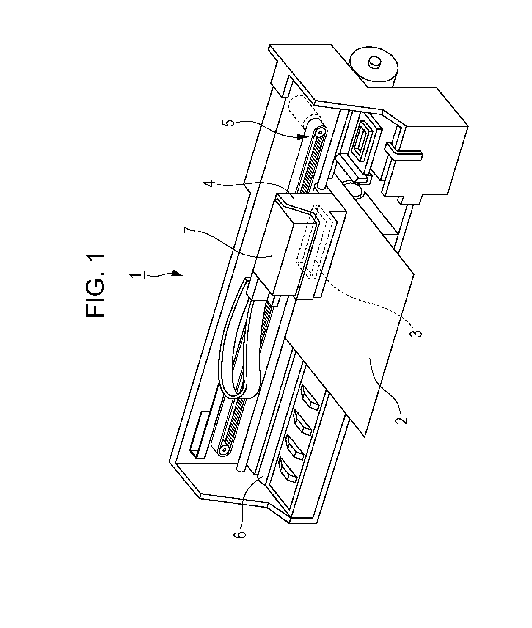
[0033]The following describes the structure of a printer 1 with reference to FIG. 1. The printer 1 is an apparatus that ejects liquid inks onto the surface of a recording medium 2 such as recording paper, and records an image or the like. The printer 1 includes a recording head 3, a carriage 4, a carriage movement mechanism 5, and a platen roller 6. The r...
PUM
 Abstract
Description
Claims
Application Information