Infinitely variable transmission for differentially steered vehicles

a technology of variable transmission and differential steering, which is applied in mechanical equipment, transportation and packaging, and gearing, etc., can solve the problem of low torque loading of the variable ratio pulley system driving the sun gear

Inactive Publication Date: 2017-01-05
INAL MEHMET KORAY
View PDF0 Cites 8 Cited by
  • Summary
  • Abstract
  • Description
  • Claims
  • Application Information

AI Technical Summary

Benefits of technology

[0016]By varying the speed and torque of the two inputs, relative to each other, to the two gear sets of a planetary gearbox, an infinitely variable output, on the third gear set, of speed and torque with forward, neutral and reverse directions is achieved. By further varying the gearing ratio differential between the two variable gear ratio inputs to the two planetary gearboxes, the desired differential steering transmission is achieved.
[0021]A variable ratio pulley is one, where one or both flanges of the pulley have a conical profile and can be moved linearly along the shaft of the pulley to vary the distance in between the two flanges. This, in turn, changes the radius at which the belt contacts the pulley, and, hence the linear speed that the belt travels at a given rotational speed of the pulley. By coupling a driver pulley and one or more driven pulleys via a belt, a variable ratio belt drive system would be achieved. By controllably varying the flange distances of some or all of the pulleys in this belt drive system, the relative rotational speeds of the driver and the driven pulleys can be varied, hence the gearing ratio between the driver and the driven pulleys. For instance in a variable ratio belt drive system of one driver and one driven pulleys, a low gearing would be achieved by setting the flanges of the driver pulley apart from each other, while setting the flanges of the driven pulley closer to each other, hence letting the belt ride the driver pulley at a smaller radius of contact compared to the driven pulley. This would result in the driven pulley to rotate slower than the driver pulley, hence the low gearing effect.
[0024]In another embodiment of this invention, two variable ratio driven pulleys, each coupled to drive each of the planet gear carrier elements of planetary gearboxes, are also coupled to each other and to a fixed ratio driver pulley via single belt. The fixed ratio driver pulley is connected to the engine output shaft. The engine is also drivingly connected to the ring gears of both planetary gearboxes via a fixed gear ratio driver. By varying the gearing ratio of the variable ratio driven pulleys in synchronization with each other, motion in forward, reverse and neutral directions with varying magnitude of speed and torque are achieved. By varying the gearing ratio of the two driven pulleys in differential amounts relative to each other, differential speeds between the two outputs shafts, hence the steering is achieved. An idler tension pulley maintains the required tension on the belt, as belt slack changes due to varying of the pulleys' ratios.
[0025]In another embodiment of this invention, in a similar setup to the previous embodiment, the two variable ratio driven pulleys are coupled to a driver pulley that is, however, a variable ratio pulley, again via single belt. One or both flanges of the driver pulley may be spring loaded, pushing towards each other, hence maintaining the tension on the belt, helping eliminate the tension idler pulley and providing for a wider range of gearing. Again by varying the gearing ratios of both driven variable ratio pulleys in synchronization with each other, motion in forward, reverse and neutral directions with varying magnitudes of speed and torque are achieved. By varying the gearing ratios of the two driven pulleys in differential amounts relative to each other, the steering is achieved.
[0026]In another embodiment of this invention, a variable ratio driver pulley with spring loaded flanges is coupled with a variable ratio driven pulley via single belt. The flanges of the driven pulley are disconnected from each other, and each flange is coupled to a respective planetary gearbox. Each flange can controllably be moved back and forth along a straight line parallel to the flange-belt contact surface angle, in a direction closer to or away from the driver pulley. By moving the flanges in the same direction and amount, hence making them closer and farther from each other, varying forward, reverse and neutral motion control is achieved. By moving flanges in differential amounts or directions, the differential speeds and hence the steering is achieved. The spring loaded flanges of the driver pulley move closer to or apart from each other in response to the controlled varying of the driven pulley ratio to maintain the belt tension, as well as to contribute to the overall belt drive system gear ratio varying.

Problems solved by technology

This setup results in the low torque loading on the variable ratio pulley system driving the sun gear.

Method used


Image

  • Infinitely variable transmission for differentially steered vehicles
  • Infinitely variable transmission for differentially steered vehicles
  • Infinitely variable transmission for differentially steered vehicles

Examples


first embodiment

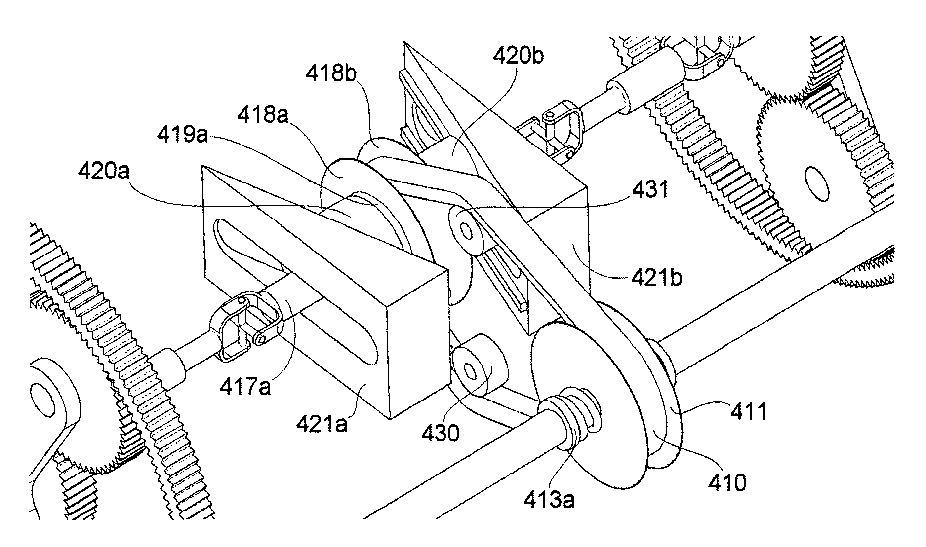
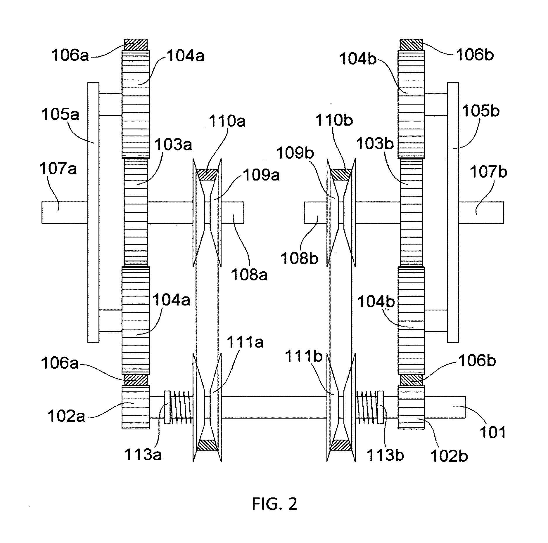
[0044]FIG. 2 and FIG. 3 illustrate an Infinitely Variable Transmission in accordance with this invention. The engine shaft 101, driven by the engine, drives the ring gears 106a 106b of both planetary gearboxes via the respective fixed gear ratio drivers 102a 102b. Hence, both ring gears 106a 106b are driven at the same speed relative to each other. The engine shaft 101 is also coupled with the two spring loaded 113a 113b variable ratio driver pulleys 111a 111b, each of which is coupled with a respective variable ratio driven pulley 109a 109b via a respective belt 110a 110b, to form two variable ratio belt drive systems. The springs 113a 113b maintain a force load on one or both flanges of both of the driver pulleys 111a 111b, pushing the flanges towards each other. Within each variable ratio belt drive system, the gearing ratio of the driven pulley 109a(109b) is controllably varied, while the ratio of the driver pulley 111a(111b) is, in response, controlled by the spring 113a(113b) ...

second embodiment

[0048]Referring to FIG. 4 and FIG. 5 as this invention, an engine 22 is drivingly connected to a fixed ratio driver pulley 211, and to a fixed gear ratio driver 202 via the engine shaft 201. A single belt 210 couples the fixed ratio pulley 211 with two variable ratio driven pulleys 209a 209b. The fixed ratio driver gear 202 is drivingly connected to the ring gears 206a 206b of both planetary gearboxes. Similar to embodiment one, planet gear sets 204a 204b of both planetary gearboxes are each coupled to drive the respective output shafts 207a 207b via the respective carrier elements 205a 205b, which in turn drive the respective tracks of the vehicle. Again similar to embodiment one, sun gears 203a 203b are drivingly connected to the respective driven pulleys 209a 209b via the respective shafts 208a 208b. Also operationally similar to embodiment one, by controllably varying the distances between the flanges, hence the gearing ratios, of both variable ratio driven pulleys 209a 209b in ...

third embodiment

[0049]A third embodiment as outlined in FIG. 6 and FIG. 7 is similar to embodiment two, however differs from embodiment two by the fact that it utilizes a spring loaded 313 variable ratio driver pulley 311, in place of the fixed ratio driver pulley 211 of embodiment two, and the tensioner pulley 212 is absent. Similar to the spring loaded 113a 113b driver pulleys 111a 111b in embodiment one, the spring load 313 for the driver pulley 311 maintains a force load on one or both flanges towards each other. As the gearing ratios of the driven pulleys 309a 309b are controllably varied, the ratio of the driver pulley 311 varies in response, under the spring load, to maintain the belt 310 tension. This spring loaded 313 ratio-varying function of the driver pulley 311 in response to the controlled ratio-varying function of the driven pulleys 309a 309b also allows for the overall belt drive pulley system to deliver a wider range of gearing ratio compared to embodiment two, for similarly sized ...


PUM


Abstract

An infinitely variable transmission system for differentially steered vehicles comprises two planetary gearboxes, each coupled to drive, as output, a driving component, such as track or wheel, on either side of a vehicle. The planetary gearboxes are drivingly coupled to a power source, such as an engine or motor, via fixed gear ratio driver and via belt drive system of two or more variable ratio belt drive pulleys. Each of the two outputs of the transmission can independently and simultaneously be controlled to revolve in forward, neutral (stop), and reverse directions in a manner of continuously and infinitesimally variable speed and torque.

Description

CROSS REFERENCES TO RELATED APPLICATIONS[0001]Not applicableSTATEMENT REGARDING FEDERALLY SPONSORED RESEARCH OR DEVELOPMENT[0002]Not applicableTHE NAMES OF THE PARTIES TO A JOINT RESEARCH AGREEMENT[0003]Not applicableINCORPORATION-BY-REFERENCE OF MATERIAL SUBMITTED ON A COMPACT DISC OR AS A TEXT FILE VIA THE OFFICE ELECTRONIC FILING SYSTEM (EFS-WEB)[0004]Not applicableSTATEMENT REGARDING PRIOR DISCLOSURES BY THE INVENTOR OR A JOINT INVENTOR[0005]Not applicableBACKGROUND OF THE INVENTION[0006]Field of the Invention[0007]The present invention relates to infinitely variable transmission systems to be used to transmit one input of torque and speed, to two outputs with independently varying speeds and torques in forward, reverse and neutral (stop) directions, suitable to be used for differentially steered vehicles.[0008]Description of the Related Art[0009]Differential steering transmission systems are widely used in a range of vehicles from zero-turn lawn mowers to tracked vehicles such ...

Claims


Application Information

Patent Timeline
Patent Type & Authority Applications(United States)
IPC IPC(8): B62D11/10F16H37/02F16H37/06F16H9/20
CPCB62D11/105F16H9/20F16H2200/2007F16H37/065F16H37/022F16H37/0813F16H37/0846F16H2037/088
Inventor INAL, MEHMET KORAY
Owner INAL MEHMET KORAY
Why Eureka
Try Eureka