Infrared resolution and contrast enhancement with fusion
Active Publication Date: 2017-01-05
FLIR SYST AB
View PDF1 Cites 9 Cited by
Summary
Abstract
Description
Claims
Application Information
AI Technical Summary
This helps you quickly interpret patents by identifying the three key elements:
Problems solved by technology
Method used
Benefits of technology
[0012]One or more embodiments of the present disclosure may solve or at least minimise the problems mentioned above. This is achieved by a method, an imaging device, and/or a non-transitory computer program product according to the claims, where an IR image is combined with high spatial frequency content of a visual image to yield a combined image. According to embodiments, the imaging device comprises a processing unit (e.g., a processor, a programmable logic device, or other type of logic device) configured to perform any or all
Problems solved by technology
A number of technical problems arise when attempti
Method used
Image
Click on the blue label to locate the original text in one second.
Reading with bidirectional positioning of images and text.
Examples
Embodiment Construction
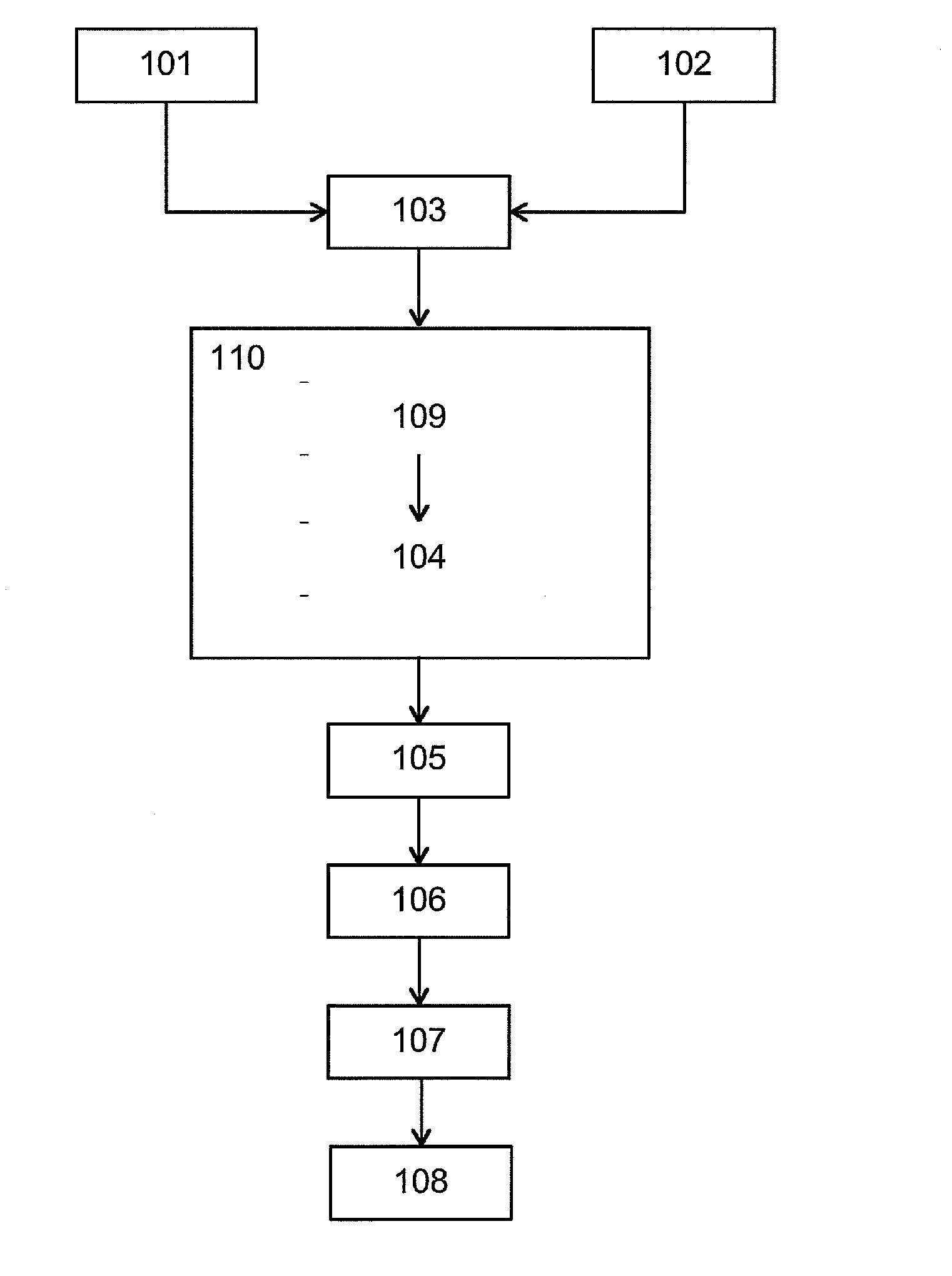
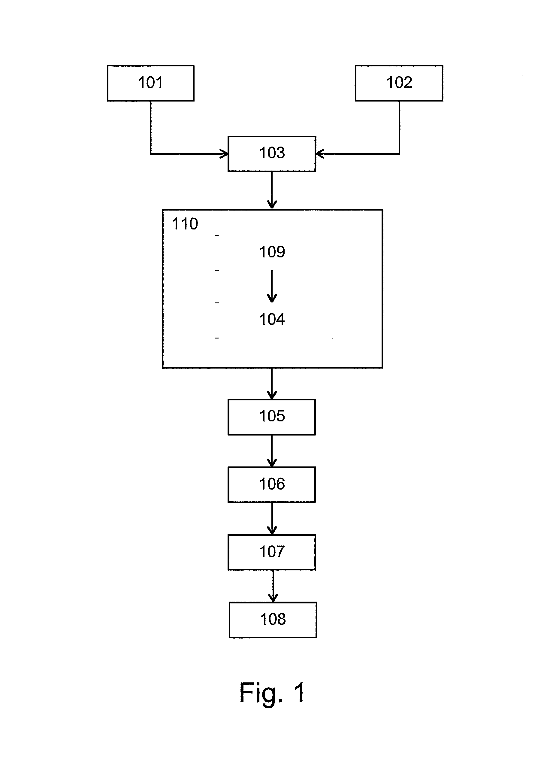
[0051]In FIG. 1, an exemplary method according to an embodiment of the present disclosure can be seen. At block 101 a visual image is captured and at block 102 an IR image is captured. The visual image and IR image may be captured by an optical sensor and an IR sensor, respectively. After capture, the visual image and the IR image may be aligned at block 103 to compensate for the parallax between the optical axes that generally arises due to differences in placement of the sensors for capturing said images and the angle created between these axes because of mechanical tolerances that generally prevents them being mounted exactly parallel.
[0052]The blocks 101, 102 can be performed simultaneously or one after the other. In one example, the images may be captured at the same time or with as little time difference as possible, since this will decrease the risk for alignment differences due to movements of an imaging device unit capturing the visual and IR images. As is readily apparent ...
PUM
Abstract
The present disclosure relates to combination of images. A method according to an embodiment comprises: receiving a visual image and an infrared (IR) image of a scene and for a portion of said IR image extracting high spatial frequency content from a corresponding portion of said visual image. The method according to the embodiment further comprises combining said extracted high spatial frequency content from said portion of the visual image with said portion of the IR image, to generate a combined image, wherein the contrast and/or resolution in the portion of the IR image is increased compared to the contrast and/or resolution of said received IR image.
Description
CROSS REFERENCE TO RELATED APPLICATIONS[0001]This patent application is a continuation of U.S. patent application Ser. No. 14 / 922,076, filed Oct. 23, 2015. U.S. patent application Ser. No. 14 / 922,076 is a continuation of U.S. patent application Ser. No. 13 / 437,645, filed Apr. 2, 2012. U.S. patent application Ser. No. 13 / 437,645 is a continuation-in-part of U.S. patent application Ser. No. 12 / 766,739, filed Apr. 23, 2010. U.S. patent application Ser. No. 13 / 437,645 also claims the benefit of U.S. Provisional Patent Application No. 61 / 473,207, filed Apr. 8, 2011. U.S. patent application Ser. No. 13 / 437,645 is also a continuation-in-part of U.S. patent application Ser. No. 13 / 105,765, filed May 11, 2011, which is a continuation of PCT Patent Application No. PCT / EP2011 / 056432, filed Apr. 21, 2011, which is a continuation-in-part of U.S. patent application Ser. No. 12 / 766,739, filed Apr. 23, 2010. U.S. patent application Ser. No. 13 / 105,765 is also a continuation-in-part of U.S. patent a...
Claims
Application Information
Patent Timeline
Application Date:The date an application was filed.
Publication Date:The date a patent or application was officially published.
First Publication Date:The earliest publication date of a patent with the same application number.
Issue Date:Publication date of the patent grant document.
PCT Entry Date:The Entry date of PCT National Phase.
Estimated Expiry Date:The statutory expiry date of a patent right according to the Patent Law, and it is the longest term of protection that the patent right can achieve without the termination of the patent right due to other reasons(Term extension factor has been taken into account ).
Invalid Date:Actual expiry date is based on effective date or publication date of legal transaction data of invalid patent.