Energy storage apparatus

a technology of energy storage and energy storage devices, which is applied in the direction of current conducting connections, batteries, cell components, etc., can solve the problems of difficulty in and achieve the effect of easy changing the number of energy storage devices

Active Publication Date: 2017-01-05
GS YUASA INT LTD
View PDF2 Cites 10 Cited by
  • Summary
  • Abstract
  • Description
  • Claims
  • Application Information

AI Technical Summary

Benefits of technology

[0006]An object of the present invention to provide an energy storage apparatus which can easily change the number of energy storage devices.

Problems solved by technology

Accordingly, it is difficult to change the number of energy storage devices.

Method used


Image

  • Energy storage apparatus
  • Energy storage apparatus
  • Energy storage apparatus

Examples


first embodiment

[0049]First, the configuration of an energy storage apparatus 1 is described.

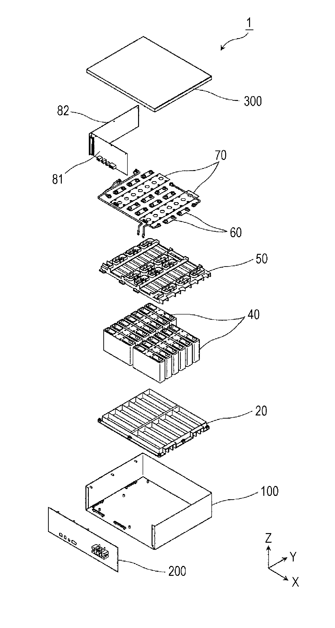
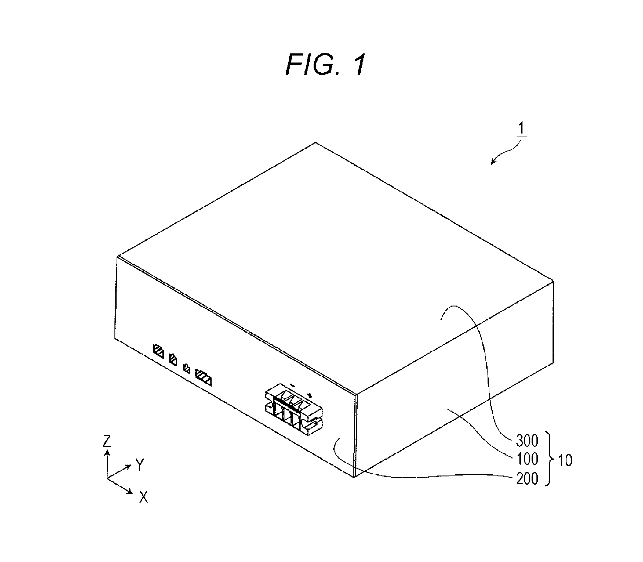
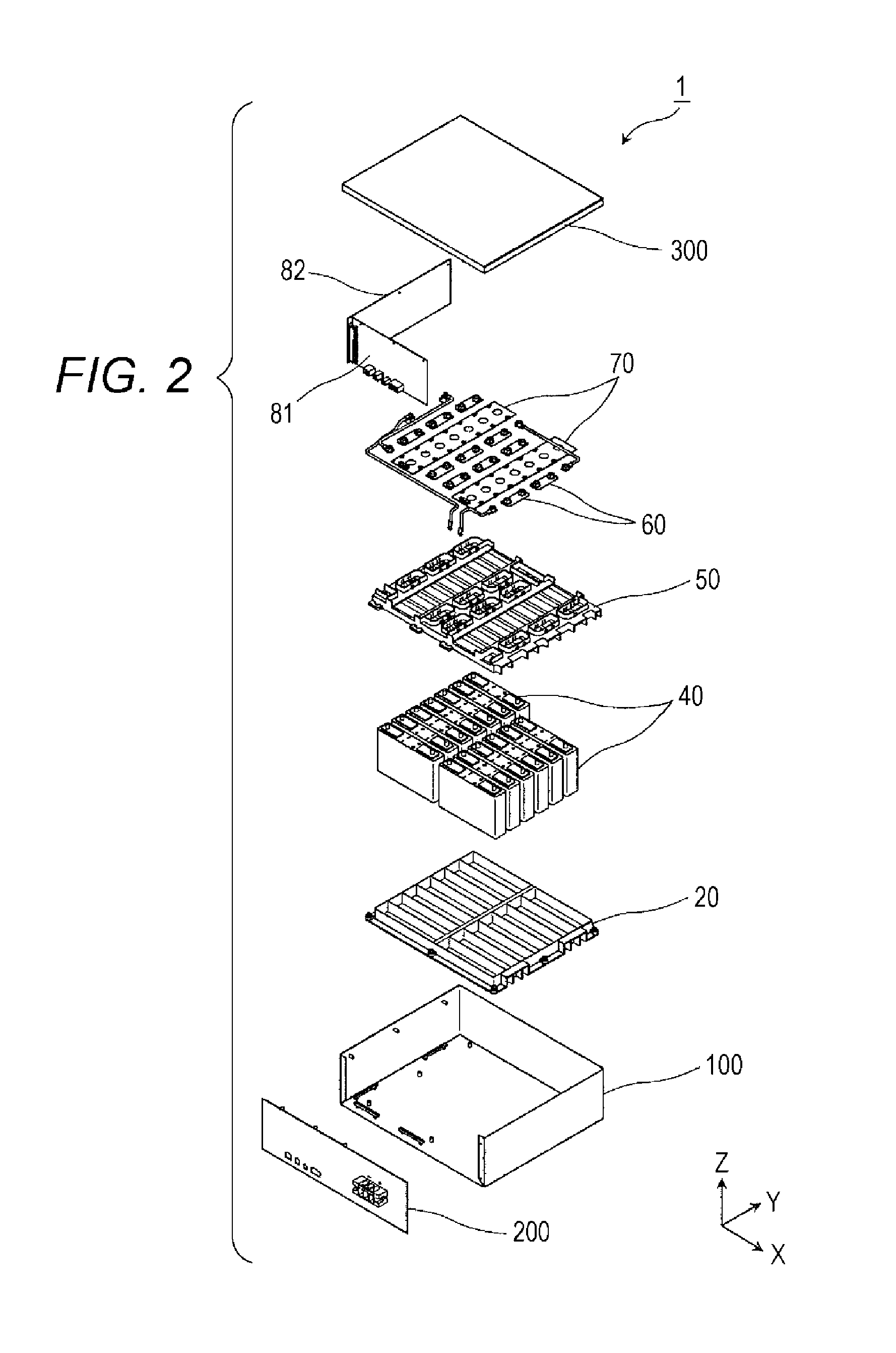
[0050]FIG. 1 is a perspective view showing the external appearance of the energy storage apparatus 1 according to the embodiment of the present invention. FIG. 2 is an exploded perspective view showing respective constitutional elements in a state where the energy storage apparatus 1 is disassembled.

[0051]In these drawings, a Z axis direction is indicated as a vertical direction. Although the description will be made hereinafter assuming the Z axis direction as the vertical direction, a case is also considered where the Z axis direction is not assumed as the vertical direction depending on a use mode. Accordingly, the Z axis direction is not limited to the vertical direction. For example, there is no problem in assuming an X axis direction as the vertical direction.

[0052]The energy storage apparatus 1 is an apparatus capable of charging electricity into an inner space therein from the outside and dischargin...

second embodiment

[0135]Next, the configuration of a terminal neighboring member 50 according to the second embodiment is described in detail. Same symbols are given to parts which are substantially equal to the parts used in the first embodiment.

[0136]FIG. 10 is a perspective view showing the configuration of the terminal neighboring member 50. FIG. 11 is a perspective view showing the positional relationship between the terminal neighboring member 50, energy storage devices 40 and bus bars 60.

[0137]As shown in these drawings, the terminal neighboring member 50 is a member which is disposed on a side where electrode terminals of the plurality of energy storage devices 40 (thirteen energy storage devices 401 to 413 in this embodiment) are disposed, and a plurality of bus bars 60 (twelve bus bars 60 in this embodiment) and conductive members 61 to 63 are disposed above the terminal neighboring member 50. The terminal neighboring member 50 includes a conductor disposing portion 510, a conductor disposi...


PUM

PropertyMeasurementUnit
conductiveaaaaaaaaaa
shapeaaaaaaaaaa
degree of freedomaaaaaaaaaa

Abstract

Provided is an energy storage apparatus which includes a first energy storage device having a first terminal which is either a positive electrode terminal or a negative electrode terminal, wherein the energy storage apparatus further includes a terminal neighboring member which is disposed adjacently to the first terminal of the first energy storage device, and the terminal neighboring member includes: a first housing portion capable of housing a first conductive member which connects the first terminal and a second terminal which a second energy storage device different from the first energy storage device has to each other; and a first lead-out portion capable of leading out a second conductive member which connects the first terminal and a third terminal which a third energy storage device different from the first energy storage device and the second energy storage device has to each other from the first housing portion.

Description

CROSS-REFERENCE TO RELATED APPLICATIONS[0001]This application claims the benefit of Japanese patent applications No. 2015-132240 filed on Jun. 30, 2015, and No. 2015-182300 filed on Sep. 15, 2015, which are incorporated by reference.FIELD[0002]The present invention relates to an energy storage apparatus provided with energy storage devices.BACKGROUND[0003]As an energy storage apparatus provided with energy storage devices, conventionally, there has been known an energy storage apparatus having the configuration where electrode terminals of energy storage devices disposed adjacently to each other are connected by a bus bar (see JP-A-2010-225583, for example).SUMMARY[0004]The following presents a simplified summary of the invention disclosed herein in order to provide a basic understanding of some aspects of the invention. This summary is not an extensive overview of the invention. It is intended to neither identify key or critical elements of the invention nor delineate the scope of ...

Claims


Application Information

Patent Timeline
Patent Type & Authority Applications(United States)
IPC IPC(8): H01M2/20H01M10/0525H01M2/02H01M2/10H01M2/30H01M2/06H01M50/119H01M50/176H01M50/209H01M50/296H01M50/50H01M50/503H01M50/507H01M50/55H01M50/553
CPCH01M50/50H01M50/553H01M50/119H01M50/55H01M50/176H01M50/503H01M50/507H01M50/209H01M50/296H01M2220/20Y02E60/10H01M50/269H01M50/298H01M50/509H01M50/271H01M50/588H01G11/78H01G11/76H01G11/80H01G11/82H01G11/08H01G11/10H01M10/0525H01G11/06Y02E60/13H01M50/20H01M50/531
Inventor MIYAWAKI, YASUTAKA
Owner GS YUASA INT LTD
Why Eureka
Try Eureka