
Hand Rest

Active Publication Date: 2017-01-12
POPPY KING PROJECTS LLC
View PDF8 Cites 5 Cited by
  • Summary
  • Abstract
  • Description
  • Claims
  • Application Information

AI Technical Summary

Benefits of technology

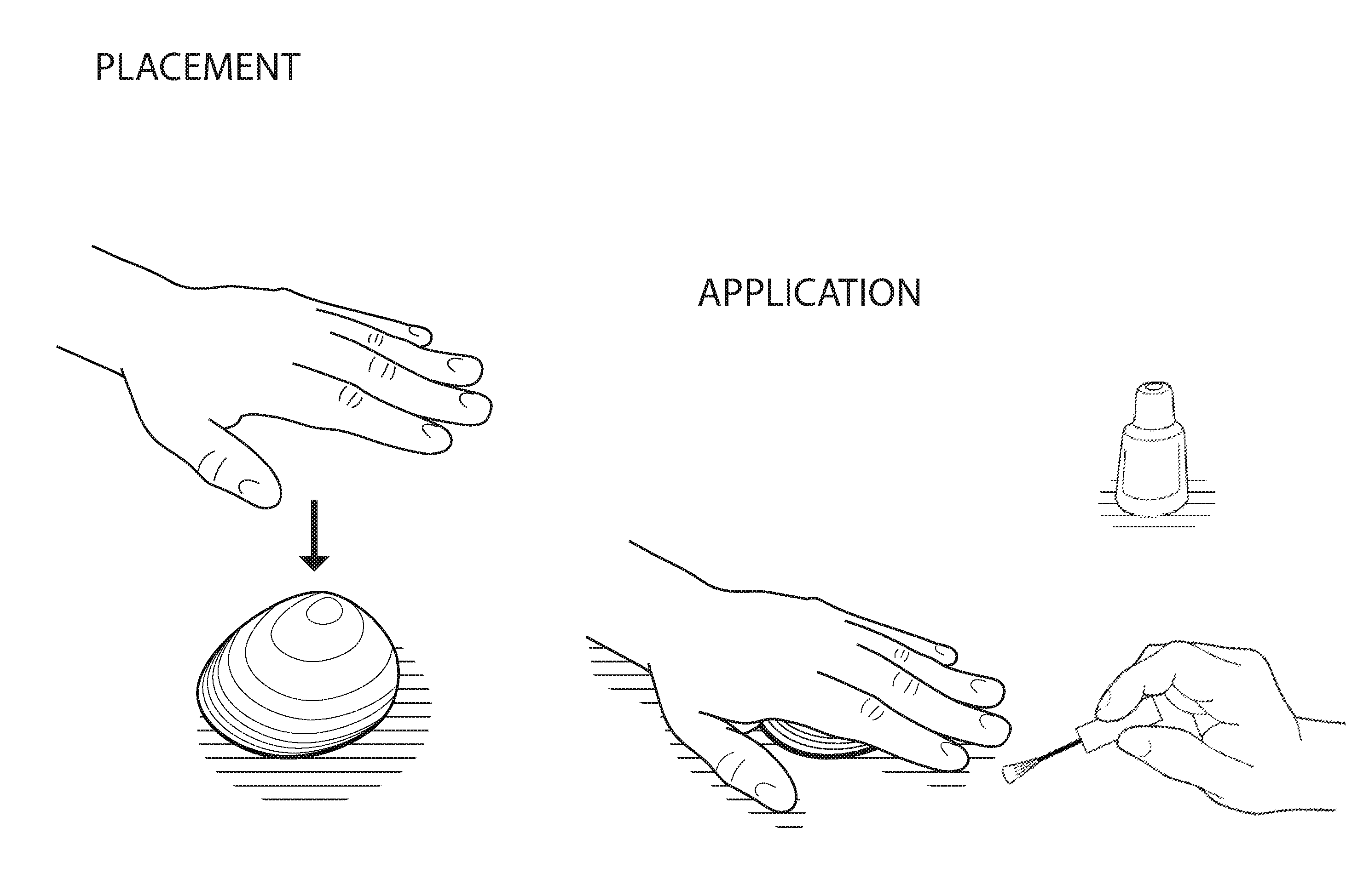
The device described in this patent helps improve the application of nail polish and manicure to the nails. It stabilizes the user's hand and angles the nails so that liquid paint can be applied evenly without pooling near the cuticle. It also allows the user to apply polish to the nail next to the cuticle without overloading it. The device can be made in solid or hollow interior construction, and it can slide easily on the supporting surface for easy manicure manipulation.

Problems solved by technology

Unfortunately, it is difficult to obtain the appearance of a professional manicure when doing one's own nails.
First, most nail salons use professional grade products or tools, e.g., cuticle oil or remover, electric nail files, and UV or LED drying lamps, that are not accessible to non-professionals or those outside the industry.
Second, it is more difficult for an individual to obtain the desired brush angle and stroke (e.g., between approximately 70 to 90 degrees with respect to the nail and in line with the length of the finger) when polishing his / her own nails than when one's nails are being painted by someone else.
Third, the precision required to create a neat, clean, even polish on all of one's nails, on both hands, is complicated by unsteady hands, and awkward angles / decreased nail visibility without moving the hands, etc.
When an individual needs to use the non-dominant hand to paint the nails on the dominant hand, most people notice a decrease in the quality of the resulting manicure, e.g. stray polish on the cuticle surrounding the nail or a messy or streaky or uneven polish.
While these devices may increase comfort for the individual having his / her nails painted and while the wrist rest devices may be somewhat helpful to the nail technician, they fail to stabilize the hand and the finger in a fixed position (the palm and fingers are unsupported between the finger tips and the wrist rest allowing the palm and fingers to move up and down) and they are not practical for use when doing one's own nails.

Method used


Image

  • Hand Rest
  • Hand Rest
  • Hand Rest

Examples


Embodiment Construction

[0036]The accompanying drawings, which are incorporated in and constitute a part of this specification, illustrate embodiments of the invention and, together with the general description of the invention given above and the detailed description of an embodiment given below, serve to explain the principles of the present invention. Similar components of the devices are similarly numbered for simplicity.

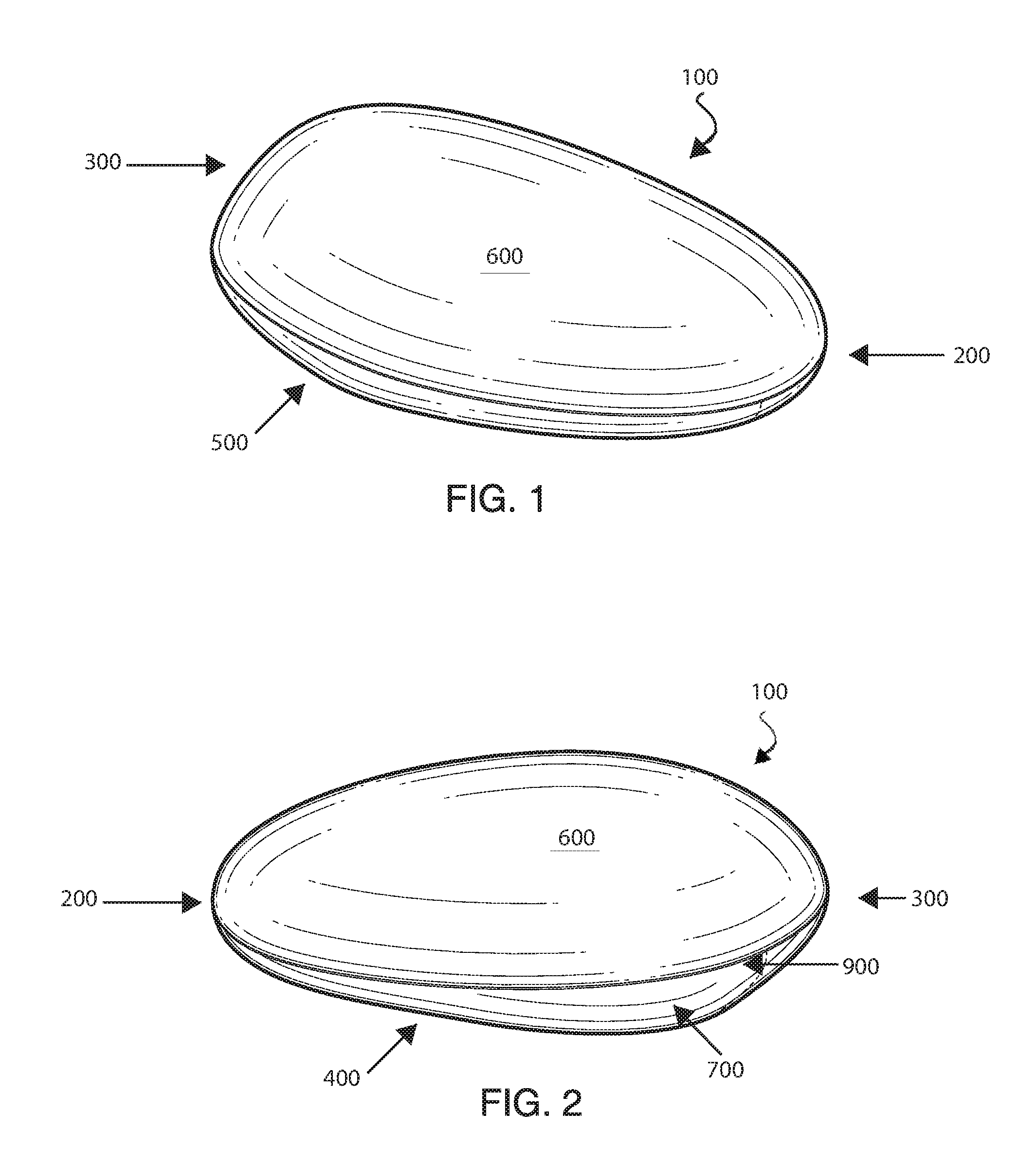
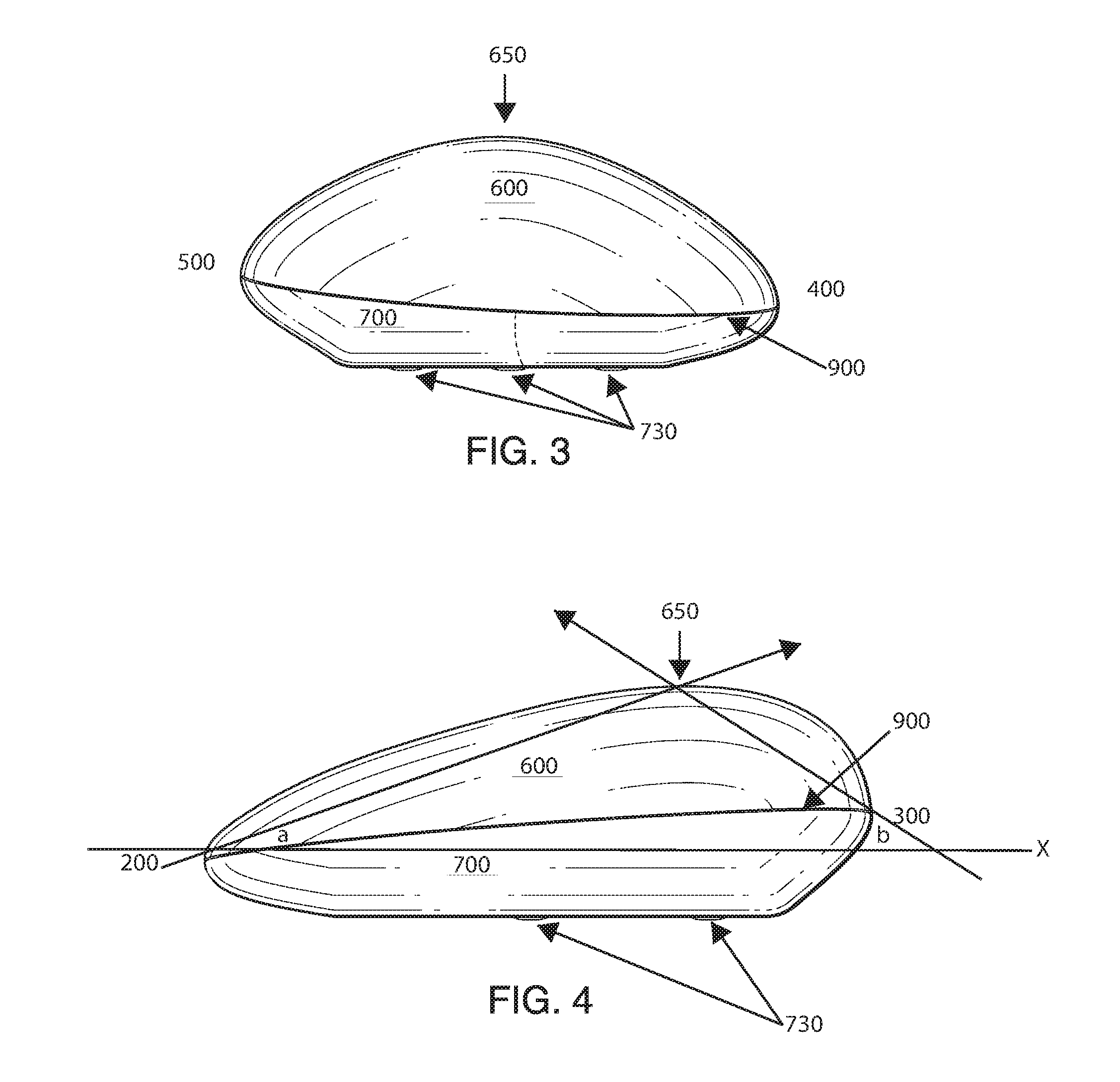
[0037]FIGS. 1-10 show one example embodiment of the hand rest 100 according to the invention. The device has a generally convex upper surface with a rounded peak located near the back end of the device that fits comfortably under a user's palm allowing the palm to bend around and onto the convex top surface of the device.

[0038]The device 100 comprises a front 200, a back 300, a right side 400, a left side 500, a top surface 600, and a bottom surface 700. The top surface 600 is configured in a generally convex rounded / curved shape having a rounded peak 650 located near the back of the t...


PUM


Abstract

A hand rest device for use during the application of nail polish comprising a front, a back, a right side, a left side, a top surface, and a bottom surface, with said top surface configured in a generally convex shape having a rounded peak positioned near the back half of the top surface longitudinally and about the middle of the top surface laterally. The top surface of the device curves down from said peak to an outer edge of the hand rest device. The bottom surface is configured with a curved portion from the outer edge of the hand rest device (around the perimeter) down to a generally flat portion, the generally flat portion further comprising a plurality of rubber pads. The device could include a weight inside.

Description

CROSS-REFERENCE TO RELATED APPLICATION[0001]This application claims the benefit of U.S. Application Ser. No. 62 / 191,022 filed on Jul. 10, 2016 which is expressly incorporated herein in its entirety by reference thereto.FIELD OF THE INVENTION[0002]The invention relates generally to hand rests for use in connection with the application of nail polish to finger nails. More specifically, the invention relates to hand rest devices that create comfort for an individual having his / her nails manicured and / or polished. The invention is also a hand rest device that, when used, improves the appearance of self-applied nail polish.BACKGROUND OF THE INVENTION[0003]Manicures are a popular way of caring for the nails and hands and ensuring they look clean and professional. A manicure typically consists of trimming, filing, and shaping the free edge of the nail, pushing back the cuticles, and clipping any cuticles or hangnails from the nail plate. Next, the nail technician may massage the hands and ...

Claims


Application Information

Patent Timeline
IPC IPC(8): A45D29/22
CPCA45D29/22A45D29/00
Inventor KING, POPPY
Owner POPPY KING PROJECTS LLC
Learn More