
Rotating shaft coupling

Active Publication Date: 2017-07-27
JAGUAR LAND ROVER LTD
View PDF1 Cites 1 Cited by
  • Summary
  • Abstract
  • Description
  • Claims
  • Application Information

AI Technical Summary

Benefits of technology

The patent describes a new coupling design for transmitting power in a vehicle drive-line. The design uses a clamp nut that is tightened progressively to ensure a secure connection between the male and female components. This reduces the chance of the coupling becoming unbalanced and creating excessive noise or causing damage to the bearings. The sliding fit between the components eliminates the need for a flange coupling, reducing the risk of run-out and improving the overall performance of the drive-line.

Problems solved by technology

Imbalance may be noticeable to the vehicle driver and vehicle occupants, and may induce noise and vibration in the vehicle structure and driveline in addition to reducing the life of bearings associated therewith.
Run-out, as a result of non-axial connection can result in generation of significant out of balance forces.
Simple flange connections provide for fixing axially and radially, but do not eliminate the possibility of run-out at the coupling, and hence imbalance.

Method used


Image

  • Rotating shaft coupling
  • Rotating shaft coupling
  • Rotating shaft coupling

Examples


Embodiment Construction

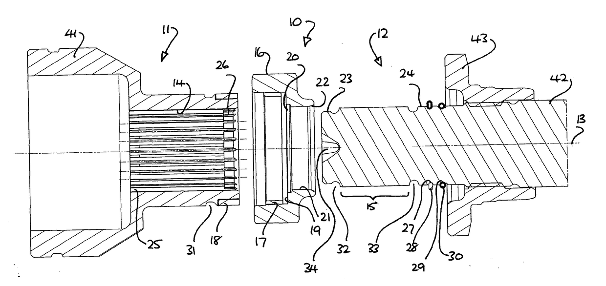
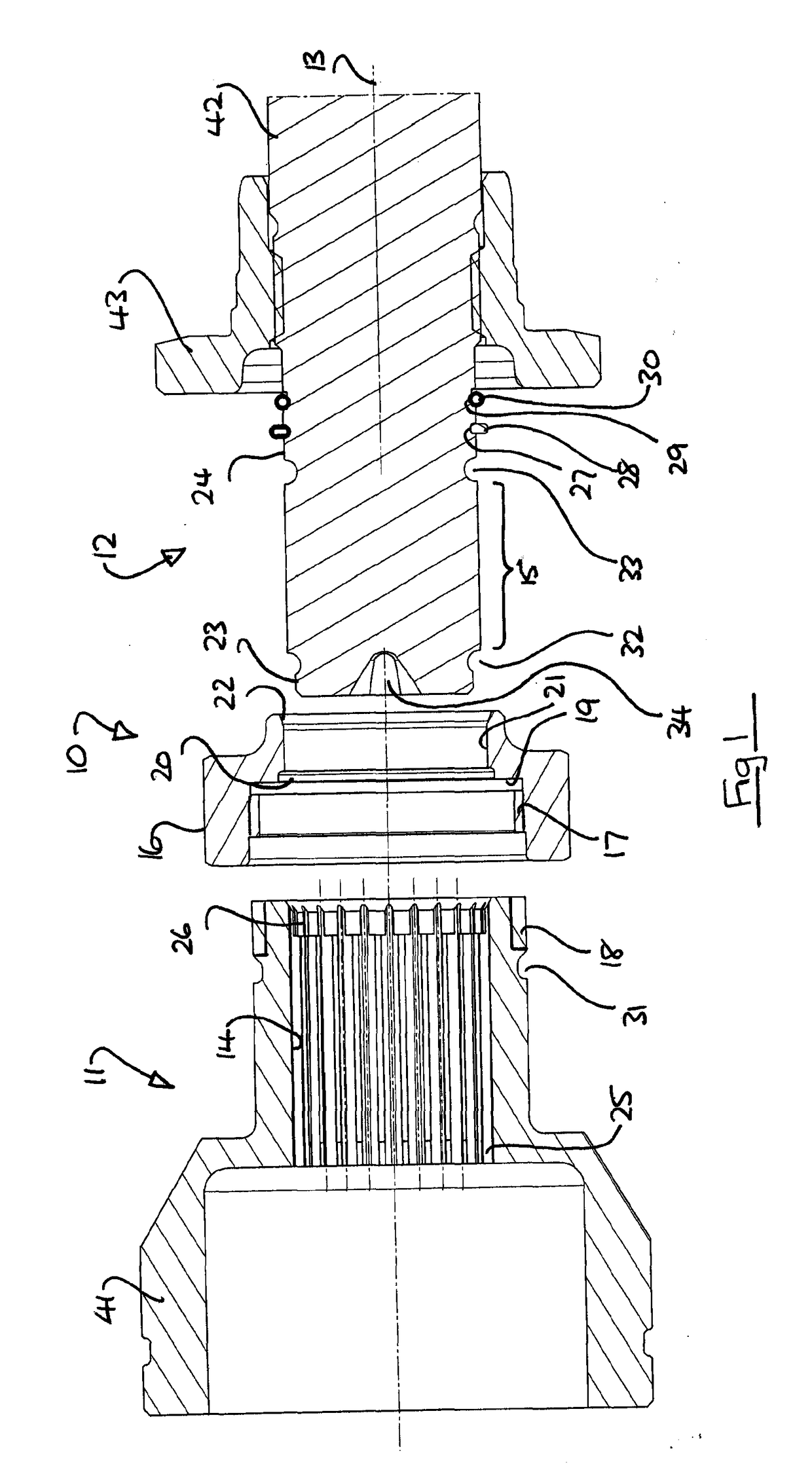
[0032]With reference to the drawings, a rotary joint assembly 10 consists of a female component 11 and a male component 12, having a rotational axis 13. The female component 11 includes internal splines 14 for sliding engagement with external splines 15 of the male component 12, thereby to transmit torque about the axis 13.

[0033]An annular clamp nut 16 has an internal thread 17 for engagement with an external thread 18 on the exterior of the female component 11 adjacent the mouth of the splines 14. In the disassembled condition the clamp nut 16 is loose, as illustrated.

[0034]The through passage of the nut 16 is stepped to provide a shoulder 19 at the base of the internal thread 17, and the lesser diameter portion 21 is sized to receive the male component 12 with a small clearance. The mouth of the lesser diameter portion 21 has a chamfer 22 to ease insertion of the male component 12 in use.

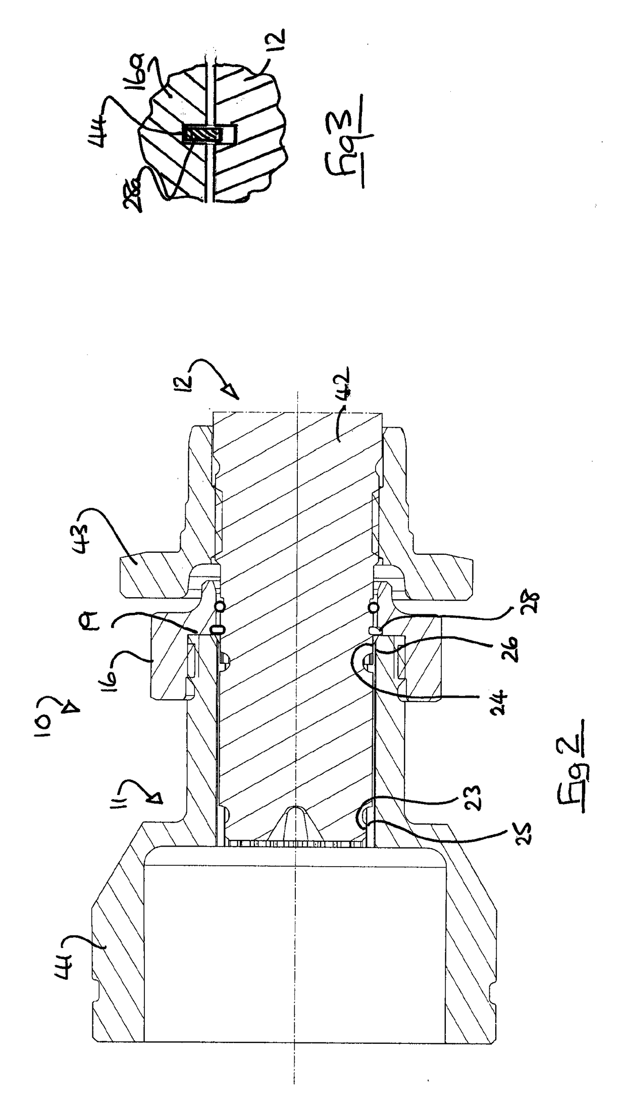
[0035]Adjacent the shoulder 19, a circular recess 20 is provided to accommodate a locking ring...


PUM


Abstract

A rotary shaft coupling (10) for the drive-line of a vehicle includes a female component (11) of a propeller shaft (41) and a male component (12) of a drive axial pinion (42). The components have mutually engageable splines (14, 15) and circular regions (23, 25, 24, 26) drawn into engagement by a clamp nut (16) of the male component; the circular regions are a sliding or an interference fit. The clamp nut (16) may also be used to draw the components (11, 12) apart.

Description

TECHNICAL FIELD[0001]This invention relates to a coupling for a rotating shaft, in particular a propeller shaft of a vehicle.BACKGROUND TO THE INVENTION[0002]A typical motor vehicle, such as a car, may have an internal combustion engine at a distance from a drive axle. A propeller shaft transmits torque from the engine to the axle, usually via a multi-speed transmission. In the most common arrangement the transmission is in unit with the engine, but the transmission may alternatively be in unit with the drive axle.[0003]A propeller shaft is typically 1-2.5 m long, and may include one or more support bearings towards the centre thereof. Where a vehicle has several drive axles, a propeller shaft may be provided for each of them.[0004]A propeller shaft should be rotationally balanced if intended to turn at speed, as is the case in a vehicle. Typically in a vehicle, a propeller shaft must be designed for rotation at engine speed without exhibiting significant out of balance forces.[0005...

Claims


Application Information

Patent Timeline
IPC IPC(8): F16D1/08F16D1/108
CPCF16D1/0858F16D2001/103F16D1/108Y10T403/7033F16D1/04F16D1/0876
Inventor TAVENER, STUART
Owner JAGUAR LAND ROVER LTD
Learn More