Transfer laminate donor for lenticular images with anti-stick backing material

Inactive Publication Date: 2005-01-25
EASTMAN KODAK CO
View PDF3 Cites 1 Cited by
  • Summary
  • Abstract
  • Description
  • Claims
  • Application Information

AI Technical Summary

Benefits of technology

and bearing on the bottom side of the support,d) an anti-stick layer that reduces the tendency of

Problems solved by technology

However, there is a problem with this method in that low resolution images are obtained, since heat transferred from the resistive head undesirably “spreads” through the support during printing and the image is therefore lacking in resolution.
This invention works well initially but over time and in the presence of high humidity, the mordanting/adhesion layer can cause blocking wherein the tr

Method used


Image

  • Transfer laminate donor for lenticular images with anti-stick backing material
  • Transfer laminate donor for lenticular images with anti-stick backing material

Examples


example 1

Element 1 of the Invention

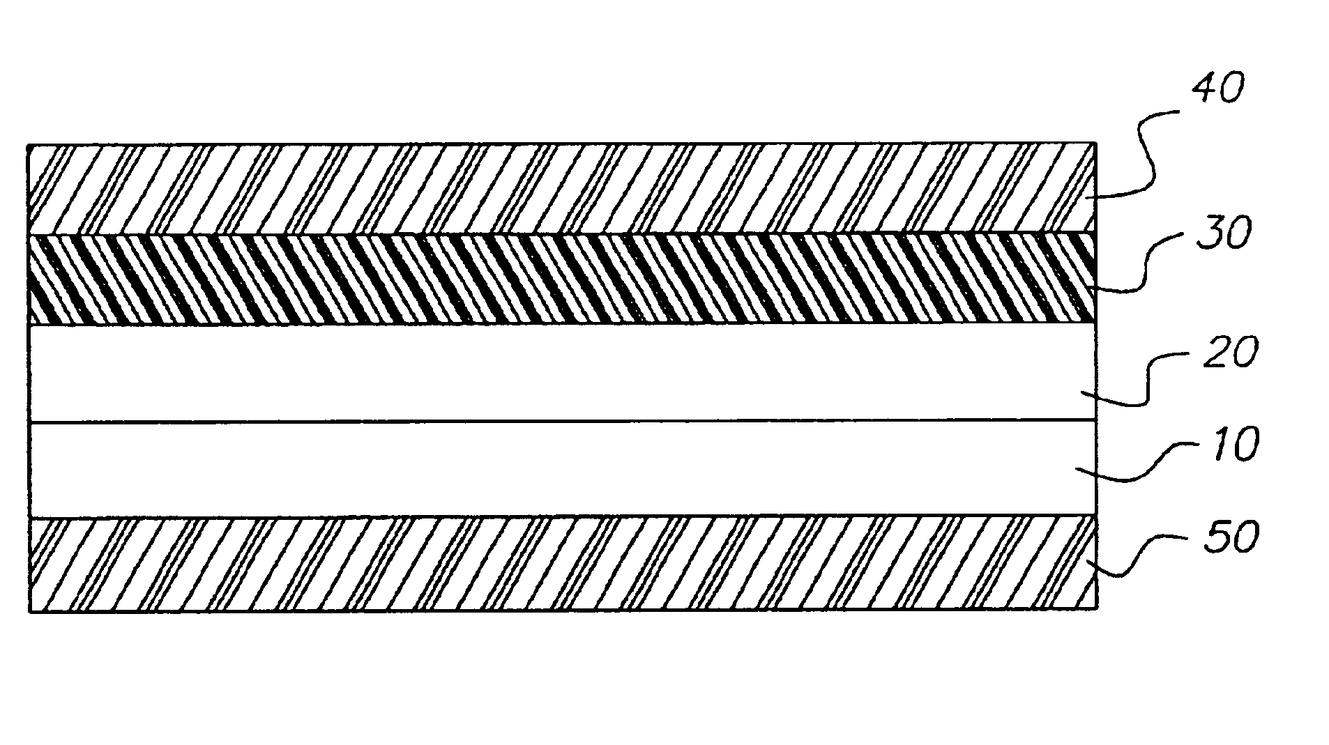
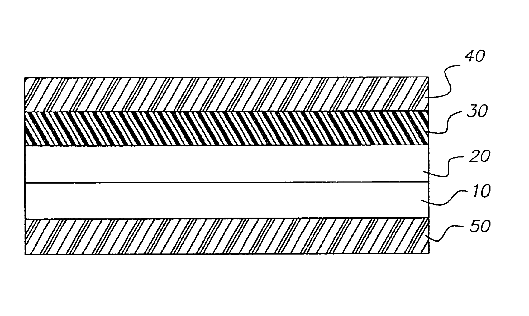
A 36 micron thick poly(ethylene terephthalate) support was coated with a release layer of polyvinylbutyral, (Butvar™ 76, Monsanto Co.), 1.08 g / m2, from acetone. On top of said release layer was coated a mordanting adhesive layer of an aqueous coating of 3.24 g / m2of the ammonia salt of poly{isophthalic acid-co-5-sulfoisophthalic acid (90:10 molar ratio)-diethylene glycol (100 molar ratio)}, MW=20,000 (ammonium salt of AQ29D, Eastman Chemical Co.) and 0.02 g / m2 Dispex N-40™, surfactant (Ciba Specialty Chemicals).

Element 2 of the Invention

This element was the same as Element 1 of the Invention except that between the release layer and the mordanting adhesive layer was coated a reflective layer of an aqueous coating of TiO2 (R706, Dupont Inc), 32.4 g / m2, and an aqueous coating of 3.24 g / m2 of the ammonia salt of poly{isophthalic acid-co-5-sulfoisophthalic acid (90:10 molar ratio)diethylene glycol (100 molar ratio)}, MW=20,000 (ammonium salt of AQ29D, Eastman Ch...


PUM

PropertyMeasurementUnit
Temperatureaaaaaaaaaa
Reflectionaaaaaaaaaa

Abstract

Disclosed is a multilayer transfer laminate donor comprising a flexible support bearing on the top side of the support:
    • a) a release layer capable of allowing the support to be removed from all layers above the release layer;
    • b) above the release layer a dye receiving layer;
    • c) on top of the transfer laminate donor, a thermal adhesion layer comprising a polymer which has a Tg less than 100° C., and that, upon application of heat, is capable of adhering to a lenticular support;
and bearing on the bottom side of the support,
  • d) an anti-stick layer that reduces the tendency of the thermal adhesion layer to stick to the bottom of the support when stored in contact therewith. Also disclosed is a process for preparing a lenticular element.
  • Description

    FIELD OF THE INVENTIONThe present invention relates to a transfer laminate donor bearing an anti-stick backing useful in the forming of a lenticular element.BACKGROUND OF THE INVENTIONLenticular arrays or overlays are a known means to give images the appearance of depth or motion. A lenticular image is created using a transparent upper layer having narrow parallel lenticules (half-cylindrical lenses) on the outer surface and an image containing substrate or lower layer that contains images viewable through the lenticules. The two layers form a lenticular system wherein images are selectively visible as a function of the angle from which the system is viewed. A depth image is a composite picture made by bringing together into a single composition a number of different parts of a scene viewed from different angles, as more fully described in U.S. Pat. No. 5,543,964. When the lenticules are vertically oriented, each eye of a viewer will see different elements and the viewer will interp...

    Claims


    Application Information

    Patent Timeline
    IPC IPC(8): B41M7/00G02B27/22G03B35/00G02B3/00G02B30/27
    CPCG02B27/2214B41M7/0027G02B30/27
    Inventor TUTT, LEE W.ANDERSON, JASON E.
    Owner EASTMAN KODAK CO
    Why Eureka
    Try Eureka