
Method for operating a system for a thermodynamic cycle with a multi-flow evaporator, control unit for a system, system for a thermodynamic cycle with a multi-flow evaporator, and arrangement of an internal combustion engine and a system

Inactive Publication Date: 2015-10-01
MOTOREN & TURBINEN UNION FRIEDRICHSHAFEN GMBH
View PDF13 Cites 2 Cited by
  • Summary
  • Abstract
  • Description
  • Claims
  • Application Information

AI Technical Summary

Benefits of technology

The invention relates to a method for operating a system for a thermodynamic cycle that reduces the tendency for instability development, even when using a multi-flow evaporator with multiple evaporator flow channels. This method ensures a stable and reliable operation of the system, attaining high power yield. Additionally, the invention provides a control unit, system, and arrangement consisting of an internal combustion engine and such a system that ensure a reduced tendency of instability development and reliable operation. The invention is achieved through a combination of methods such as making the evaporator flow channels similar to each other, automatically controlling the pressure drop across the evaporator, and adjusting the pressure drop to match a suitable normational pressure drop for the operating point of the system.

Problems solved by technology

When several evaporator flow channels of this type are operated in parallel, however, there is the problem of increased susceptibility to thermodynamic instabilities.
In particular, the so-called Ledinegg instability can occur: When vaporization begins prematurely in one of the evaporator flow channels, the pressure drop in this channel increases sharply.
This results in turn in a sharp decrease in the flow of medium through this evaporator flow channel as a result of the pressure relationships, and this causes the effect to become even more pronounced.
Thus the efficiency and the power output of the system decrease.
There is also the danger that the working medium in the blocked flow channel can become unallowably superheated.
In this case, deposits can also form, which permanently reduce the heat transfer in the evaporator and thus reduce the energy yield of the overall system over the long term.
When working medium suddenly starts to flow through the blocked evaporator flow channel again, thermal shock can occur, leading to irreversible damage at least to the evaporator flow channel in question, if not to the entire evaporator.

Method used


Image

  • Method for operating a system for a thermodynamic cycle with a multi-flow evaporator, control unit for a system, system for a thermodynamic cycle with a multi-flow evaporator, and arrangement of an internal combustion engine and a system
  • Method for operating a system for a thermodynamic cycle with a multi-flow evaporator, control unit for a system, system for a thermodynamic cycle with a multi-flow evaporator, and arrangement of an internal combustion engine and a system
  • Method for operating a system for a thermodynamic cycle with a multi-flow evaporator, control unit for a system, system for a thermodynamic cycle with a multi-flow evaporator, and arrangement of an internal combustion engine and a system

Examples


Embodiment Construction

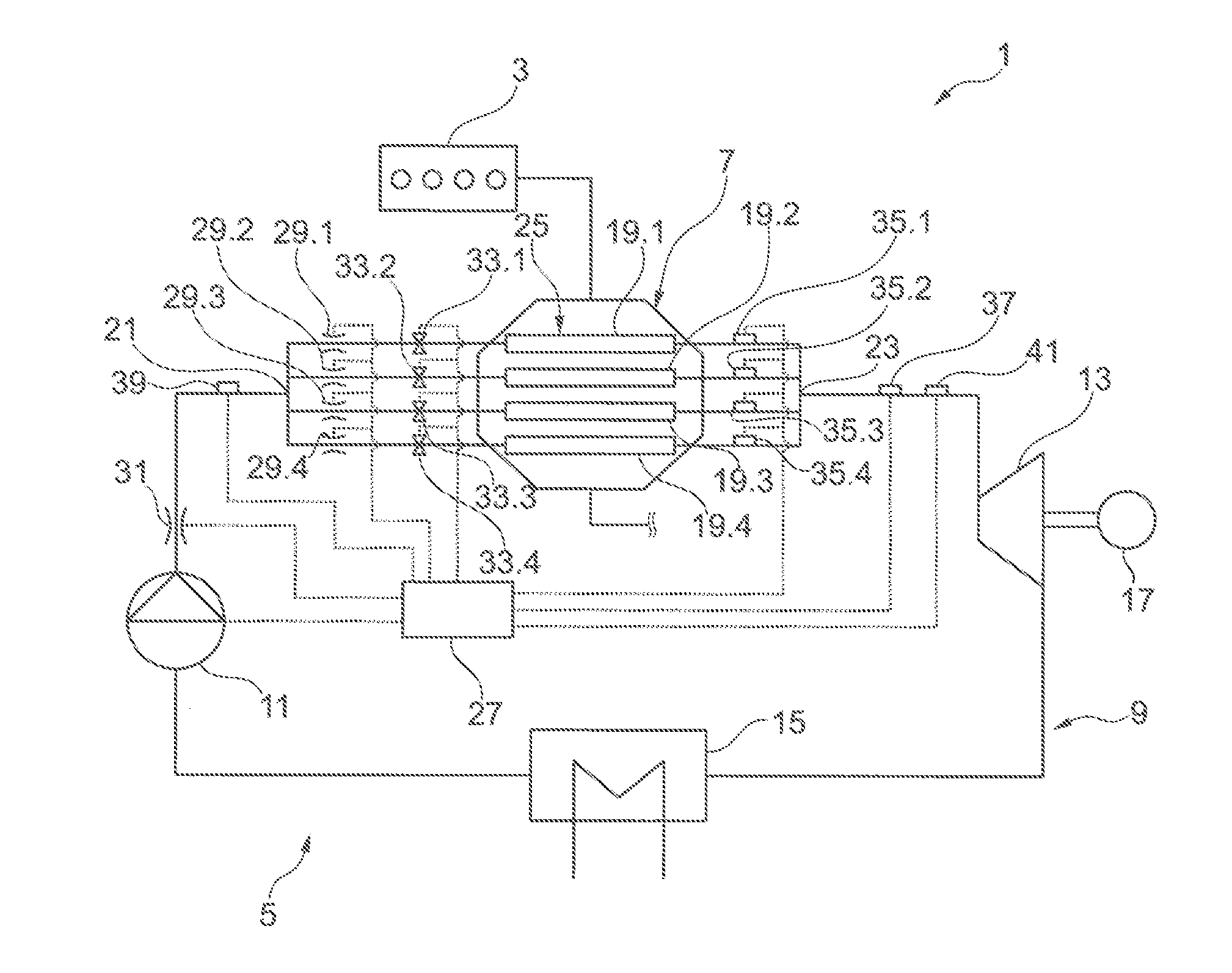
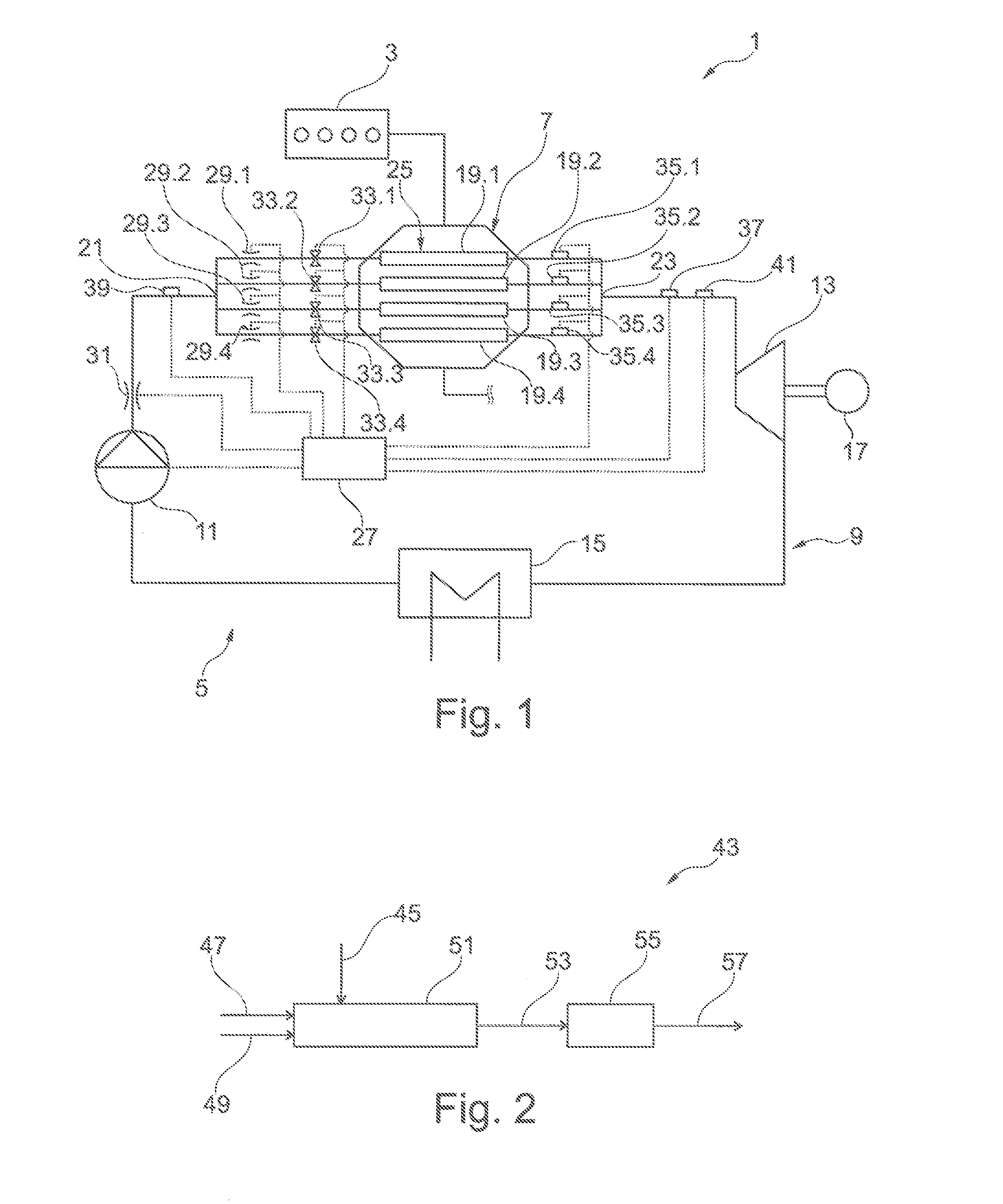
[0048]FIG. 1 shows an arrangement 1 comprising an internal combustion engine 3 and a system 5 for a thermodynamic cycle. The system 5 and the internal combustion engine 3 are functionally connected to each other in such a way that waste heat of the internal combustion engine 3 is usable in the system 5, in that the waste heat of the internal combustion engine 3 is sent to a evaporator 7 of the system 5. This waste heat is preferably the waste heat from the exhaust gas of the internal combustion engine 3, which is sent to the evaporator 7. Alternatively or in addition, it is possible for waste heat from the coolant of the internal combustion engine 3 to be used the evaporator 7.

[0049]The system 5 comprises a circuit 9 for a working medium. The system 5 is preferably set up to carry out an ORC process, wherein ethanol is used especially preferably as the working medium.

[0050]In the direction in which the working medium flows around the circuit 9, a conveying device 11, the evaporator ...


PUM


Abstract

A method for operating a system for a thermodynamic cycle with a multi-flow evaporator having at least two evaporator flow channels, wherein the evaporator flow channels are made to approximate each other with respect to at least one operating parameter of the individual evaporator flow channels, and / or wherein a pressure drop across the evaporator is automatically controlled.

Description

CROSS-REFERENCE TO RELATED APPLICATIONS[0001]The present application claims priority of DE 10 2014 206 043.5, filed Mar. 31, 2014, the priority of this application is hereby claimed and this application is incorporated herein by reference.BACKGROUND OF THE INVENTION[0002]The invention pertains to a method for operating a system for a thermodynamic cycle, to a control unit for a system for a thermodynamic cycle, to a system for a thermodynamic cycle, and to an arrangement consisting of an internal combustion engine and a corresponding system.[0003]Systems of the type in question here and methods for operating them are known. A system of this type usually comprises a circuit, through which a working medium is conveyed by a feed pump. This medium is vaporized in a evaporator and sent to an expansion device, in which it is expanded. Some of the heat absorbed by the working medium in the evaporator in converted to mechanical work. After the expansion, the working medium is cooled, in par...

Claims


Application Information

Patent Timeline
IPC IPC(8): F25B39/02
CPCF25B39/028F22B29/06F22B35/10
Inventor WAIBEL, NIKLASSTECHER, DANIELFAST, GERALDHORBACH, TIMNIEMEYER, JENSLORENZ, MAXMULLER, MATHIAS
Owner MOTOREN & TURBINEN UNION FRIEDRICHSHAFEN GMBH
Learn More