Gear machining apparatus

Active Publication Date: 2017-01-12
JTEKT CORP
View PDF12 Cites 0 Cited by
  • Summary
  • Abstract
  • Description
  • Claims
  • Application Information

AI Technical Summary

Benefits of technology

[0009]An object of the invention is to provide a gear machining apparatus that enables a reduction in machining time wh

Problems solved by technology

Since the same parts of the protruding tool edges come into contact with the work piece from roughing to finishing, the parts are significantly worn off and the tool is short-lived.
However, an envelope of the ed

Method used


Image

  • Gear machining apparatus
  • Gear machining apparatus
  • Gear machining apparatus

Examples


Embodiment Construction

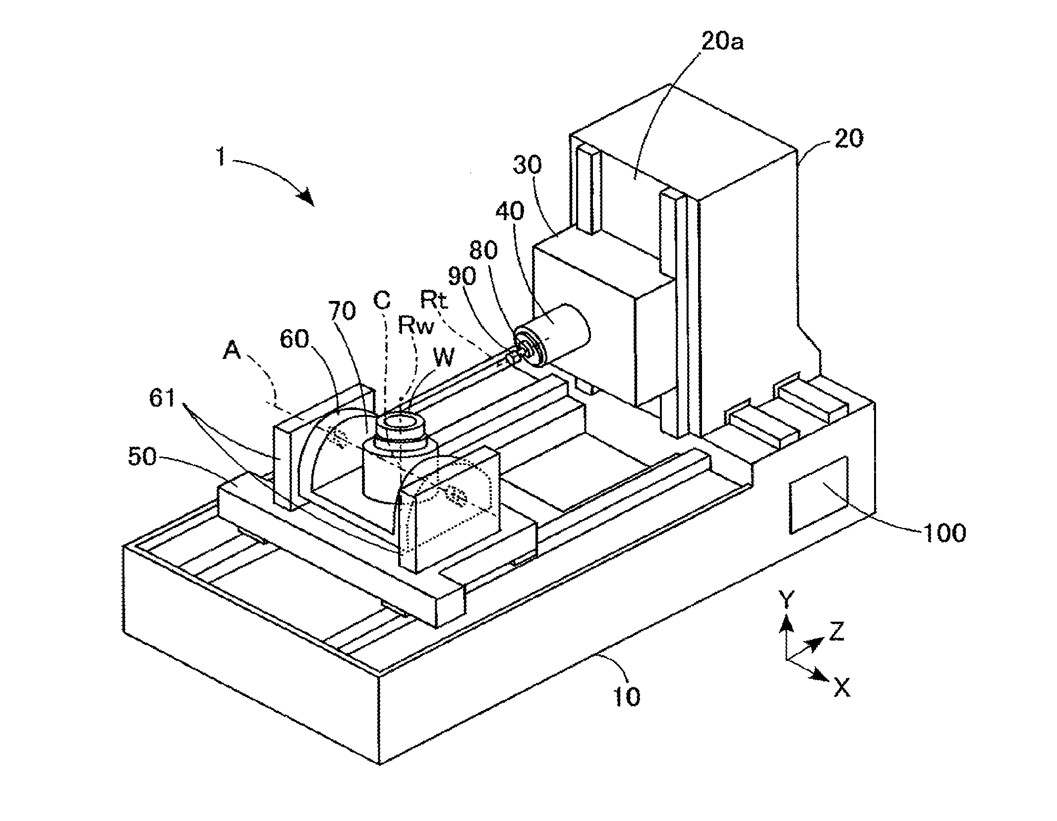
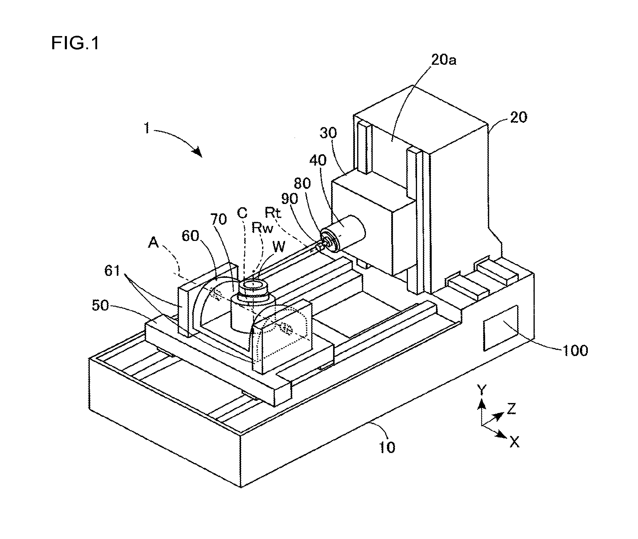
[0024]A gear machining apparatus will be described with reference to FIG. 1 taking a five-axis machining center as an example. In other words, the gear machining apparatus 1 has, as driving axes, three linear axes (X axis, Y axis, and Z axis) that are orthogonal to one another and two axes of rotation (A axis and C axis).

[0025]As depicted in FIG. 1, the gear machining apparatus 1 includes a bed 10, a column 20, a saddle 30, a rotating main spindle 40, a table 50, a tilt table 60, a turntable 70, and a control apparatus 100. Although not depicted in the drawing, a known automatic tool replacement apparatus is provided beside the bed 10.

[0026]The bed 10 is shaped generally like a rectangle and arranged on a floor. The column 20 is provided on an upper surface of the bed 10 so as to be movable in an X axis direction with respect to the bed 10. The saddle 30 is provided on a side surface (sliding surface) 20a of the column 20 that is parallel to the X axis such that the saddle 30 is mov...


PUM

PropertyMeasurementUnit
Thicknessaaaaaaaaaa
Diameteraaaaaaaaaa
Areaaaaaaaaaaa

Abstract

A gear machining apparatus includes a machining tool having a plurality of protruding tool edges on an outer periphery of the machining tool, and driving apparatuses that form a tooth on a work piece by rotating the machining tool around a central axis thereof, rotating the work piece W around a central axis thereof, and moving the machining tool relative to the work piece. Radial outer faces of the protruding tool edges form multiple steps that are parallel to the central axis of the machining tool such that the diameter of the machining tool increases in a stepwise manner from a tool leading end toward a tool base end of the machining tool.

Description

INCORPORATION BY REFERENCE[0001]The disclosure of Japanese Patent Application No. 2015-137636 filed on Jul. 9, 2015 including the specification, drawings and abstract, is incorporated herein by reference in its entirety.BACKGROUND OF THE INVENTION[0002]1. Field of the Invention[0003]The invention relates to a gear machining apparatus.[0004]2. Description of the Related Art[0005]A machining method described in Japanese Patent Application Publication No. 2012-45687 (JP 2012-45687 A), for example, is an effective technique for creating internal teeth or external teeth on a work piece by cutting using a machine tool such as a machining center. The machining method involves synchronously rotating a machining tool that is rotatable around a central axis (tool axis) and a work piece that is rotatable around a central axis (work piece axis) inclined at a predetermined angle to the tool axis of the machining tool, and feeding the machining tool in the direction of the work piece axis of the ...

Claims


Application Information

Patent Timeline
IPC IPC(8): B23F5/20B23F21/12
CPCB23F21/122B23F5/202B23F5/16B23F5/163B23F5/205Y10T409/105088Y10T409/105247Y10T409/105565Y10T409/105724Y10T409/107632
Inventor NATSUDA, KAZUKIOTANI, HISASHINAKANO, HIROYUKI
Owner JTEKT CORP
Why Eureka
Try Eureka