
Guide rail profile integrated module and manufacturing process thereof

An integrated, guide rail technology, applied in the field of guide rail modules, can solve problems such as unfavorable market competitiveness, reduce work efficiency, increase process steps, etc., and achieve the effects of saving machining time, convenient processing, and easy installation and use

Pending Publication Date: 2022-08-02
东莞市华凯科技自动化设备有限公司
View PDF0 Cites 0 Cited by
  • Summary
  • Abstract
  • Description
  • Claims
  • Application Information

AI Technical Summary

Problems solved by technology

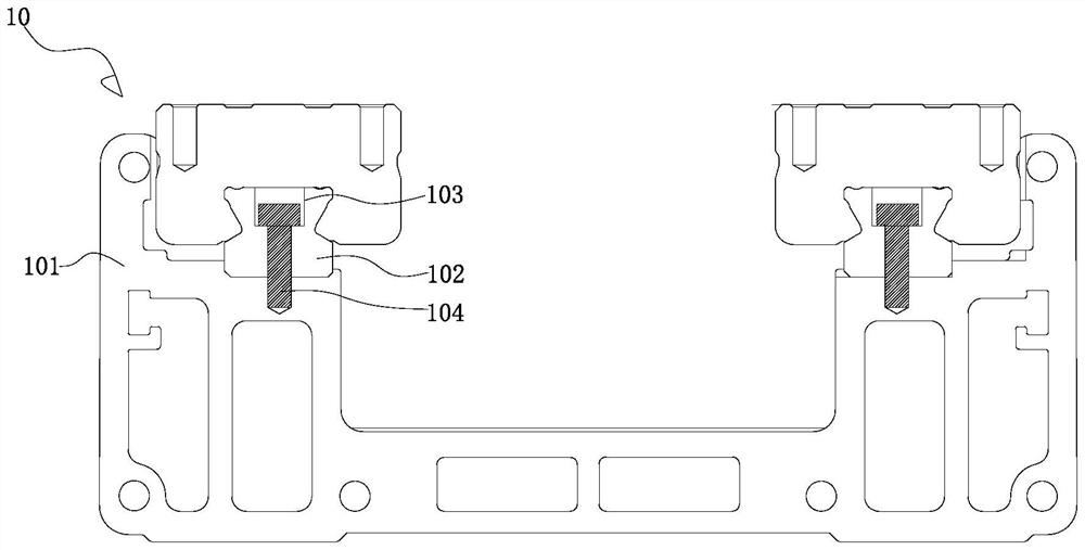
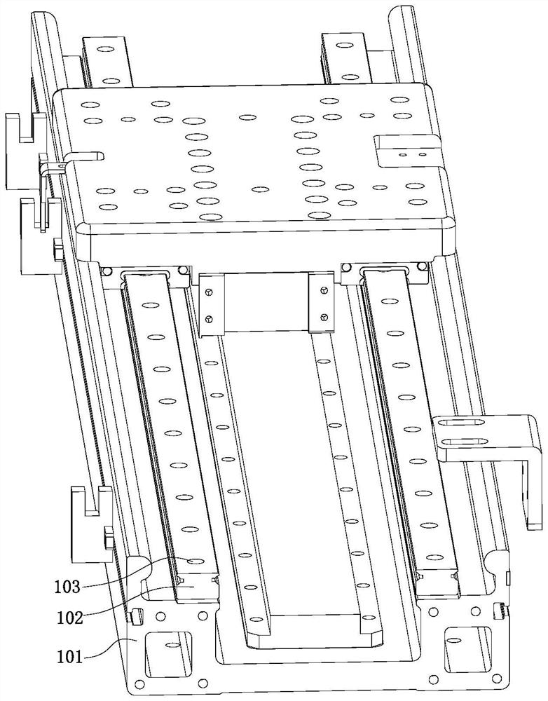
[0003] see Figure 1-Figure 2 The guide rail module 10 in the prior art generally includes an aluminum alloy profile 101 and a guide rail 102. The two guide rails 102 are respectively arranged on both sides of the upper end surface of the aluminum alloy profile 101 and protrude from the upper end surface of the aluminum alloy profile 101. Wherein, the guide rail 102 requires multiple screws to be locked on the aluminum alloy profile 101, so that it is necessary to drill and tap the guide rail 102 to form a plurality of screw holes 103. Since multiple screws 104 need to be locked, the process steps will be increased. It also increases the assembly time, and during the assembly process, it is necessary to calibrate and assemble the guide rail pair to achieve assembly accuracy, which makes installation difficult and reduces work efficiency, which is not conducive to improving market competitiveness

Method used


Image

  • Guide rail profile integrated module and manufacturing process thereof
  • Guide rail profile integrated module and manufacturing process thereof
  • Guide rail profile integrated module and manufacturing process thereof

Examples


Embodiment Construction

[0025] The present invention will be further described below with reference to specific embodiments and accompanying drawings.

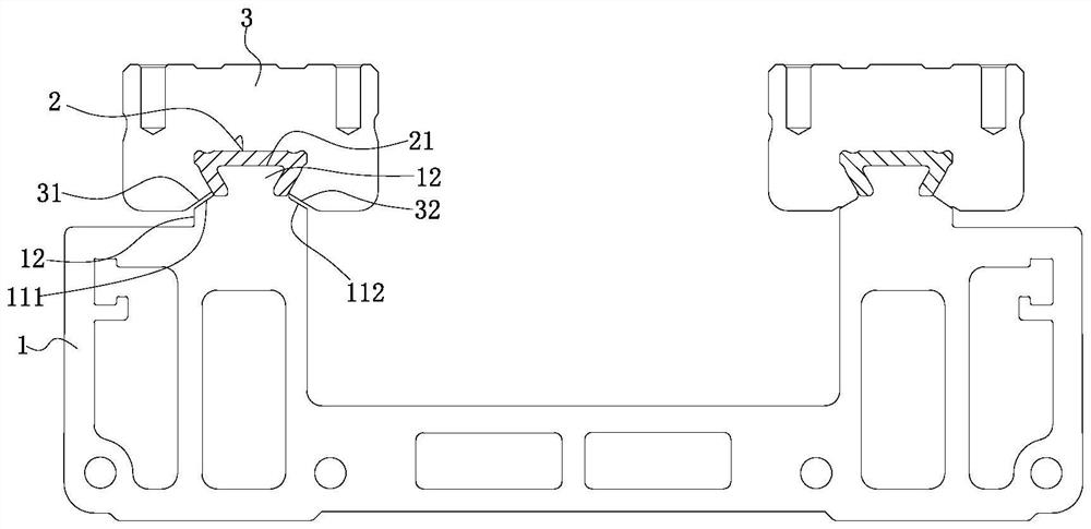
[0026] See Figure 3-Figure 4 As shown, it is an integrated module of rail profiles, which includes a carbon fiber profile 1 made of carbon fiber composite material and two rails 2 arranged on both sides of the upper end face of the carbon fiber profile 1, and the rails 2 protrude from the carbon fiber. The upper end surface of the profile 1 is outside, wherein the carbon fiber profile 1 and the guide rail 2 are fixed as a whole by means of in-mold forming. The present invention uses carbon fiber composite materials to form carbon fiber profiles 1, and replaces aluminum alloy profiles, which has lower cost, more convenient processing and manufacturing, and can also reduce the overall weight of the module, which is convenient for installation and use; in addition, the guide rail 2 and the carbon fiber profile 1 Through in-mold forming, the fixing met...


PUM


Abstract

The invention discloses a guide rail profile integrated module and a manufacturing process thereof, the guide rail profile integrated module comprises a carbon fiber profile made of a carbon fiber composite material and two guide rails arranged on the two sides of the upper end face of the carbon fiber profile, the guide rails protrude out of the upper end face of the carbon fiber profile, and the carbon fiber profile and the guide rails are fixed into a whole in an in-mold forming mode. The carbon fiber section bar is made of the carbon fiber composite material to replace an aluminum alloy section bar, so that the cost is lower, the processing is convenient, the overall weight of the module can be reduced, and the installation and the use are convenient; due to the fact that the guide rail and the carbon fiber section bar are fixed into a whole, deformation resistance strength is high, screw locking is not needed, machining time is saved, assembly precision between the guide rail and the carbon fiber section bar can be high, the guide rail can be machined into the final shape in advance, later meter calibration is not needed, parallelism can reach two to three times of meter calibration assembly precision, and the accuracy of meter calibration is improved. The guide rail is convenient to machine, machining procedures can be reduced, and product quality can be guaranteed.

Description

technical field [0001] The invention relates to the field of guide rail modules, in particular to a guide rail profile integrated module and a manufacturing process thereof. Background technique [0002] The guide rail is used to support and guide the moving parts, and perform reciprocating linear motion in a given direction. [0003] see Figure 1-Figure 2 , the guide rail module 10 in the prior art generally includes an aluminum alloy profile 101 and a guide rail 102. The two guide rails 102 are respectively arranged on both sides of the upper end surface of the aluminum alloy profile 101, and protrude outside the upper end surface of the aluminum alloy profile 101, The guide rail 102 needs multiple screws to be locked on the aluminum alloy profile 101, so that the guide rail 102 needs to be drilled and tapped to form a plurality of screw holes 103. Since multiple screws 104 need to be locked, this will increase the process steps, and at the same time The assembly time is...

Claims


Application Information

Patent Timeline
Patent Type & Authority Applications(China)
IPC IPC(8): B29C70/42B29C70/54
CPCB29C70/42B29C70/54
Inventor 彭凯雄
Owner 东莞市华凯科技自动化设备有限公司
Learn More