Grinding machine for plate-like elements, particularly ceramic tiles and plates, natural stones, glass or similar

a technology of plate-like elements and grinding machines, which is applied in the field of grinding machines for plate-like elements, can solve the problems of affecting the production efficiency of the product, the complexity of the operation setting, and the limitation of productivity, so as to achieve the effect of practical and efficient operation

Active Publication Date: 2020-05-19
ANCORA
View PDF11 Cites 0 Cited by
  • Summary
  • Abstract
  • Description
  • Claims
  • Application Information

AI Technical Summary

Benefits of technology

[0024]The main object of the present invention is to provide a grinding machine, particularly for tiles, ceramic sheet-like elements made of stone or the like, capable of square-positioning the sheet-like elements in a different manner with respect to the machines of the known type, simultaneously guaranteeing a practical and efficient operation.
[0025]An object of the present invention is to provide a machine capable of providing a simple construction solution with respect to the machines of the known type.
[0026]Still, another object of the present invention is to provide a better performing machine with respect to the machines of the known type and in particular capable of allowing the simultaneous square-positioning of a plurality of sheet-like elements, even small in size, thus increasing productivity and reducing machining times.
[0027]Another object of the present invention is to provide a grinding machine capable of overcoming the aforementioned drawbacks of the prior art through a simple and rational solution that is easy to use and relatively inexpensive.

Problems solved by technology

The machines of the known type are distinguished by the fact that they are rather complex in terms of operational settings as well as ordinary and extraordinary maintenance.
However, such adjustment interventions require stopping the machine for periods of time related to the challenges the user is faced with when intervening on such elements.
Another drawback lies in the fact that each sheet-like element requires to be square-positioned separately and this represents a productivity limitation in the operating line considering how quick the sheet-like elements are fed in sequence.
Lastly, another drawback is related to the fact that there arises the need to operate the abutment elements always at the rear side of the sheet-like elements before the front side nears the machining means.
This requires adjusting the stretch interval of the abutment elements depending on the length of the sheet-like element thus leading to the support structure of the abutment elements being heavy and complex.

Method used


Image

  • Grinding machine for plate-like elements, particularly ceramic tiles and plates, natural stones, glass or similar
  • Grinding machine for plate-like elements, particularly ceramic tiles and plates, natural stones, glass or similar
  • Grinding machine for plate-like elements, particularly ceramic tiles and plates, natural stones, glass or similar

Examples


first embodiment

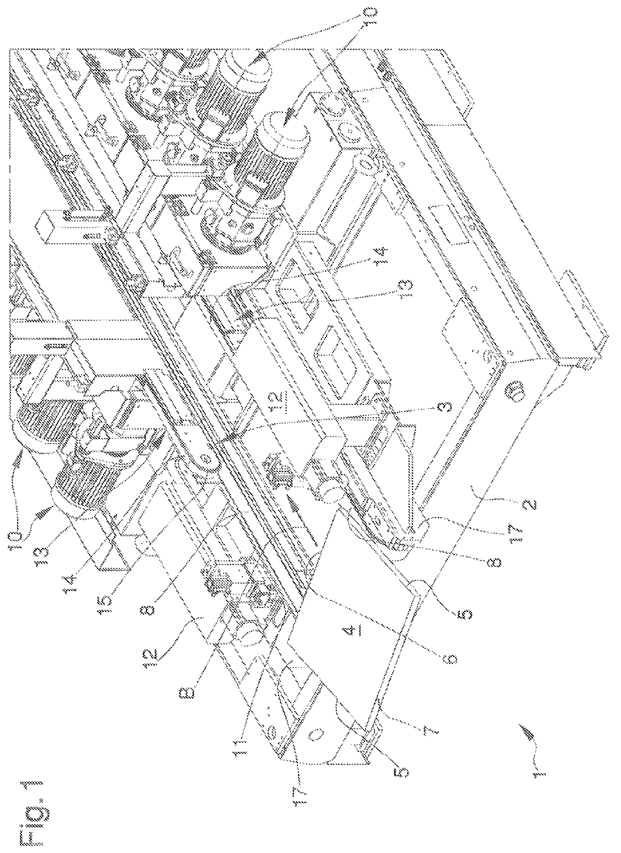
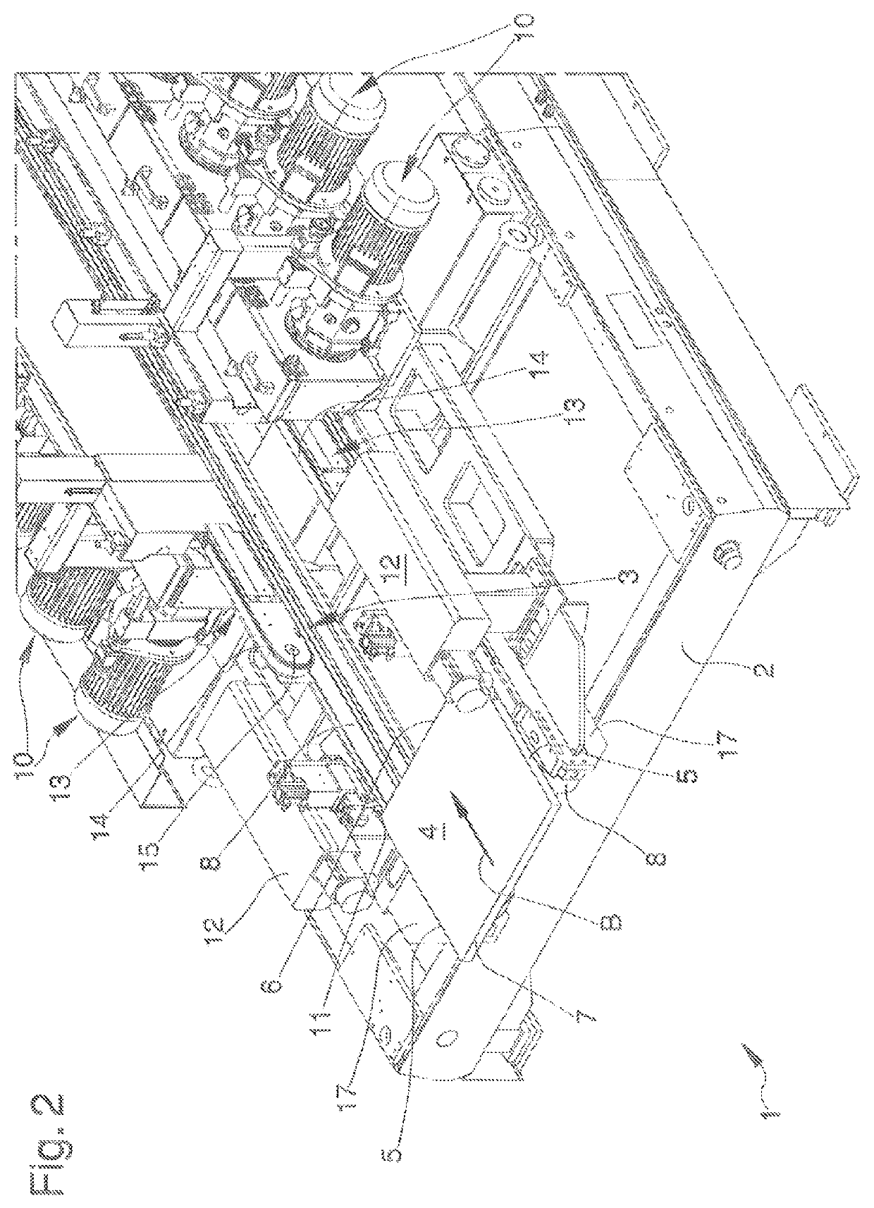
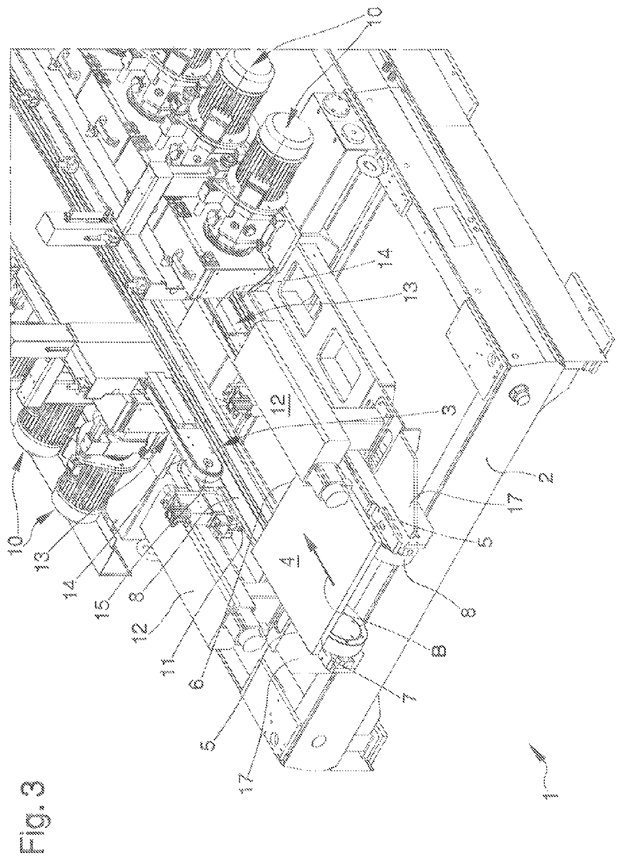
[0071]In a first embodiment, shown in FIGS. 1 to 4, the pressing means 13 comprise a pair of flexible members 14, such as belts, conveyors or the like, closed loop-like and each of which is at least partly wound around a second actuation pulley 15.

[0072]In this first embodiment, the flexible members 14 extend longitudinally with respect to the advancement direction B and they are arranged symmetrically with respect to the vertical plane longitudinal to the advancement direction.

[0073]More in detail, the flexible members 14 are arranged above the relative flexible elements 8 and they are adapted to press the sheet-like element 4 against the flexible elements.

[0074]Upon reaching the square position of the sheet-like element 4 and following the displacement of the abutment elements 11 from the operative position to the inoperative position, the sheet-like element 4 is inserted between the flexible elements 8 and the flexible members 14.

second embodiment

[0075]In a second embodiment, shown in FIGS. 5 to 7, the pressing means 13 comprise a pair of wheel units 16.

[0076]More in detail, each wheel unit 16 is arranged above a relative flexible element 8. Similarly, to the first embodiment described above, both wheel units 16 are arranged above the relative flexible elements 8 and they are symmetric with respect to the vertical plane longitudinal to the advancement direction B.

[0077]In both embodiments shown in the figures, the pressing means 13 are interposed between the abutment elements 11 along a direction transversal to the advancement direction B.

[0078]In other words, the abutment elements 11 are arranged externally with respect to the pressing means 13 to intercept the sheet-like element 4 at the end portions of the front side 6.

[0079]The present invention also regards a method for grinding sheet-like elements, particularly tiles and slabs made of ceramic material, natural stone, glass or the like, described below.

[0080]In particul...


PUM


Abstract

The machine for grinding sheet-like elements, particularly tiles and slabs made of ceramic material, natural stone, glass or the like, includes a base framework, means for advancing at least one sheet-like element on a movement plane (A) along an advancement direction (B), the sheet-like element being provided with a pair of opposite first sides to be ground and a front side transversal to the first sides and defining the advancement front of the sheet-like element, means for machining the first sides adapted to intercept the sheet-like element in the motion thereof along the advancement direction (B), means for square-positioning the sheet-like element on the movement plane (A) comprising at least one abutment element which defines at least two support points adapted to contact the front side for arranging it in a position orthogonal to the advancement direction (B).

Description

TECHNICAL FIELD[0001]The present invention regards a machine for grinding sheet-like elements, particularly tiles and slabs made of ceramic material, natural stones, glass or the like.DESCRIPTION OF RELATED ART[0002]It is known that sheet-like elements like tiles, both flooring and wall tiles, or such as marble and / or glass tiles, require a grinding operation necessary to bring the sides of the products to the ideal design shape or surface.[0003]For example, in the ceramic industry such operation is carried out through grinding machines capable of quickly machining large amounts of ceramic products which advance on a horizontal movement plane in succession.[0004]As a matter of fact, conventional grinding machines usually comprise means, of the conveyor belt type, for advancing sheet-like elements.[0005]The sides of the products to be machined project laterally from the conveyor belts and, during the advancement, they encounter a series of grinding wheels, which remove the surplus ma...

Claims


Application Information

Patent Timeline
Patent Type & Authority Patents(United States)
IPC IPC(8): B24B7/22B24B9/06B23Q3/18B24B7/26B24B9/10B27B27/10
CPCB24B7/265B24B9/102B27B27/10B23Q3/186B24B7/22B24B9/06B24B7/224
Inventor CORRADINI, MARIOSTEFANI, ANTONIO
Owner ANCORA
Why Eureka
Try Eureka