Spreading Device for a Cement Ground

a technology of cement ground and spreading device, which is applied in the direction of manufacturing tools, construction, building construction, etc., can solve the problems of large load, easy injury to the user's wrist and arm, and high work time and energy of conventional trowels, so as to achieve the effect of easy and convenient operation and change of the blade angl

Inactive Publication Date: 2017-01-12
CHEN DING NAN
View PDF1 Cites 0 Cited by
  • Summary
  • Abstract
  • Description
  • Claims
  • Application Information

AI Technical Summary

Benefits of technology

[0008]According to the primary advantage of the present invention, the control handle is rotated by the user to have a larger moment, so that the user can operate and rotate the operation handle unit in an energy-saving manner.
[0009]According to another advantage of the present invention, the control handle is operated by the user's arm to prevent the user's hand from being hurt.
[0010]According to a further advantage of the present invention, the user's two hands hold the handgrip and the control handle of the operation handle unit respectively to move the blade forward and backward, so that the user can operate and change the angle of the blade easily and conveniently in an energy-saving manner.
[0011]Further benefits and advantages of the present invention will become apparent after a careful reading of the detailed description with appropriate reference to the accompanying drawings.
[0012]FIG. 1 is a perspective view of a conventional spreading device in accordance with the prior art.
[0013]FIG. 2 is a partially exploded perspective view of the conventional spreading device as shown in FIG. 1.

Problems solved by technology

However, the blade can only spread a small region of the cement ground at a time so that the conventional trowel needs much working time and energy.
However, when the user exerts a force to rotate the handgrip 32, the elongate push bar 31 has a long force arm, and the blade 10 has a determined weight, so that the user cannot operate the handgrip 32, the elongate push bar 31 and the blade 10 easily and conveniently, thereby easily hurting the user's wrist during a long-term utilization.
In addition, the user's hand has to hold the handgrip 32 tightly so as to move the blade 10 forward and backward, thereby causing a large load to and easily hurting the user's wrist and arm.

Method used


Image

  • Spreading Device for a Cement Ground
  • Spreading Device for a Cement Ground
  • Spreading Device for a Cement Ground

Examples


Embodiment Construction

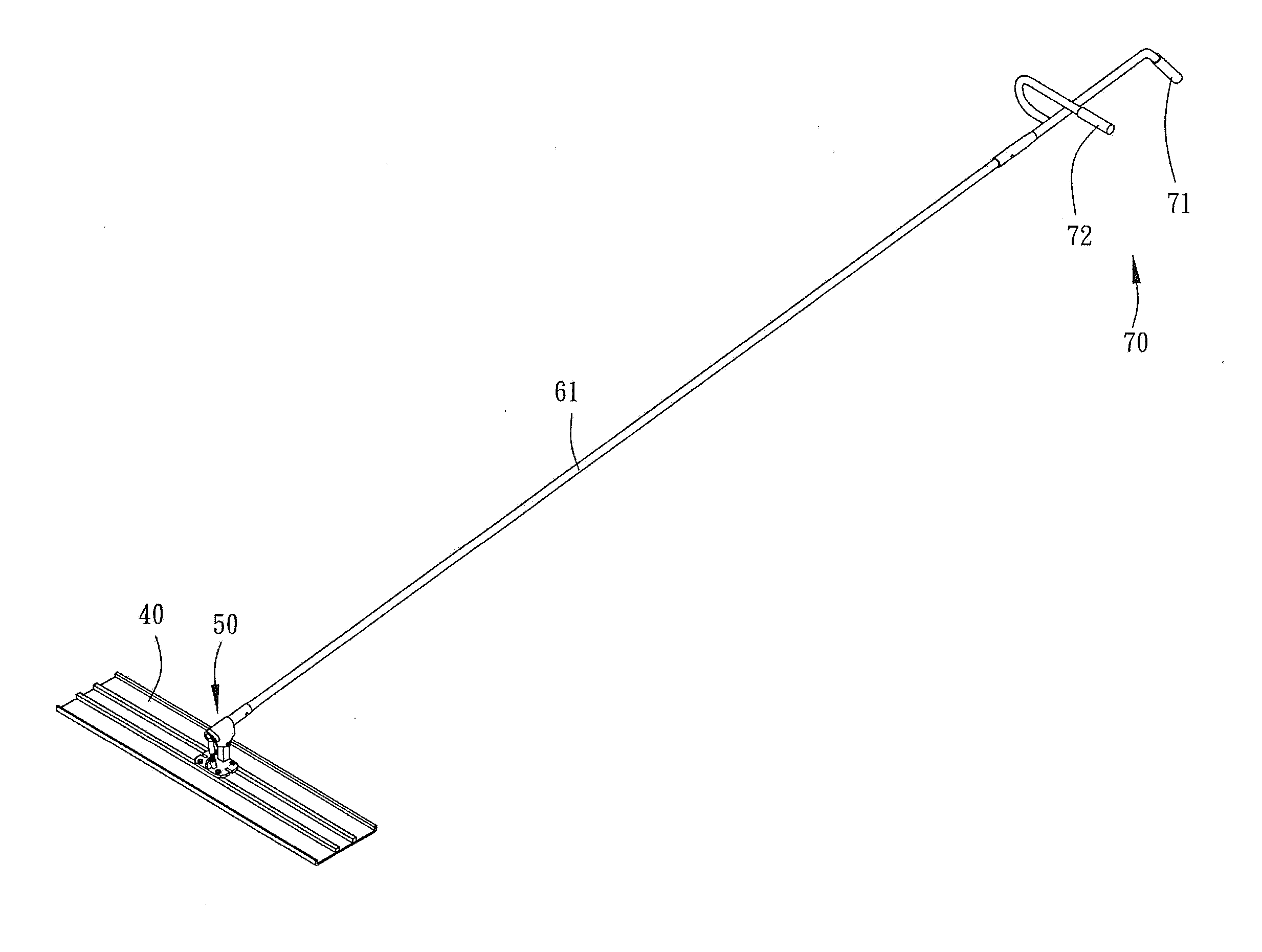
[0021]Referring to the drawings and initially to FIGS. 6 and 7, a spreading device in accordance with the preferred embodiment of the present invention comprises a large blade 40, a control structure 50 mounted on the blade 40, and an operation handle unit 70 connected with the control structure 50.

[0022]The control structure 50 includes a base 51 locked onto the blade 40, a driving stand 52 formed on the base 51, a limit stand 57 formed on the base 51, a pivoting support 55 having a bottom pivotally connected with the limit stand 57 by a screw member 56, a control rod 60 mounted on the pivoting support 55, a cam seat 54 secured on a first end of the control rod 60, a driving rod 53 having a first end pivotally mounted on a side of the driving stand 52 and a second end pivotally connected with the cam seat 54 and located at an eccentric position of the cam seat 54, and an elongate push bar 61 having a first end mounted on a second end of the control rod 60 and a second end securely ...


PUM


Abstract

A spreading device includes a blade, a control structure mounted on the blade, and an operation handle unit connected with the control structure. The control structure includes a base locked onto the blade, a driving stand formed on the base, a limit stand formed on the base, a pivoting support pivotally connected with the limit stand by a screw member, a control rod mounted on the pivoting support, a cam seat secured on a first end of the control rod, a driving rod having a first end pivotally mounted on the driving stand and a second end pivotally connected with and located at an eccentric position of the cam seat, and an elongate push bar having a first end mounted on a second end of the control rod and a second end securely connected with the operation handle unit.

Description

BACKGROUND OF THE INVENTION[0001]1. Field of the Invention[0002]The present invention relates to a spreading device and, more particularly, to a spreading device for a cement ground.[0003]2. Description of the Related Art[0004]A trowel is used to spread and trim a cement ground that is not dried and cured. The conventional trowel includes a blade with a small width and a short handgrip connected with the blade. However, the blade can only spread a small region of the cement ground at a time so that the conventional trowel needs much working time and energy. A spreading device is used to spread a cement ground with a larger area. A conventional spreading device for a cement ground in accordance with the prior art shown in FIGS. 1-5 comprises a large blade 10, and a control structure 20 mounted on the blade 10. The control structure 20 includes a base 21 locked onto the blade 10, a driving stand 22 formed on the base 21, a limit stand 27 formed on the base 21, a pivoting support 25 ha...

Claims


Application Information

Patent Timeline
Patent Type & Authority Applications(United States)
IPC IPC(8): E04F21/16B25G1/10
CPCB25G1/102E04F21/161E04F21/244
Inventor CHEN, DING-NAN
Owner CHEN DING NAN
Why Eureka
Try Eureka