
Electrical machine, in particular a generator

a generator and electric machine technology, applied in the direction of electric generator control, magnetic circuit shape/form/construction, magnetic circuit rotating parts, etc., can solve the problems of heavy equipment, heavy equipment, installation, servicing and repair, etc., and achieve low cost, easy manufacturing, and avoid eddy current

Active Publication Date: 2012-08-07
SIEMENS AG
View PDF16 Cites 6 Cited by
  • Summary
  • Abstract
  • Description
  • Claims
  • Application Information

AI Technical Summary

Benefits of technology

[0012]The primary part therefore has windings through which current can flow, with these windings advantageously being arranged in an area of the primary part which represents an outer area of the disk with respect to the disk shape. This makes it possible to achieve a large moment. A corresponding situation applies to the parts which form the secondary part. By way of example, the secondary part has permanent magnets which are positioned on the secondary part in the same radius region as the windings on the primary part. If, instead of the permanent magnets, the secondary part has only means for guidance of a magnetic field, with this means having a tooth structure, then this tooth structure is also positioned on the secondary part such that the tooth structure is opposite that part of the primary part which is intended to form the electromagnetic fields.
[0056]In a further advantageous refinement of the electrical machine, the further means for production of a magnetic field (for example a permanent magnet), which is embedded in soft-magnetic magnetic circuit sections, is arranged to concentrate the flux. The flux-concentration arrangement allows high magnetic utilization of the electrical machine. Embedding means that the permanent magnets are positioned in soft-magnetic material in such a way that a soft-magnetic material is adjacent, entirely or in places, to those sides of the permanent magnets on which the magnetic field emerges.

Problems solved by technology

This unit is very large and heavy.
Installation, servicing and repair require heavy and expensive equipment, for example heavy-lift helicopters or heavy-lift cranes.

Method used


Image

  • Electrical machine, in particular a generator
  • Electrical machine, in particular a generator
  • Electrical machine, in particular a generator

Examples


Embodiment Construction

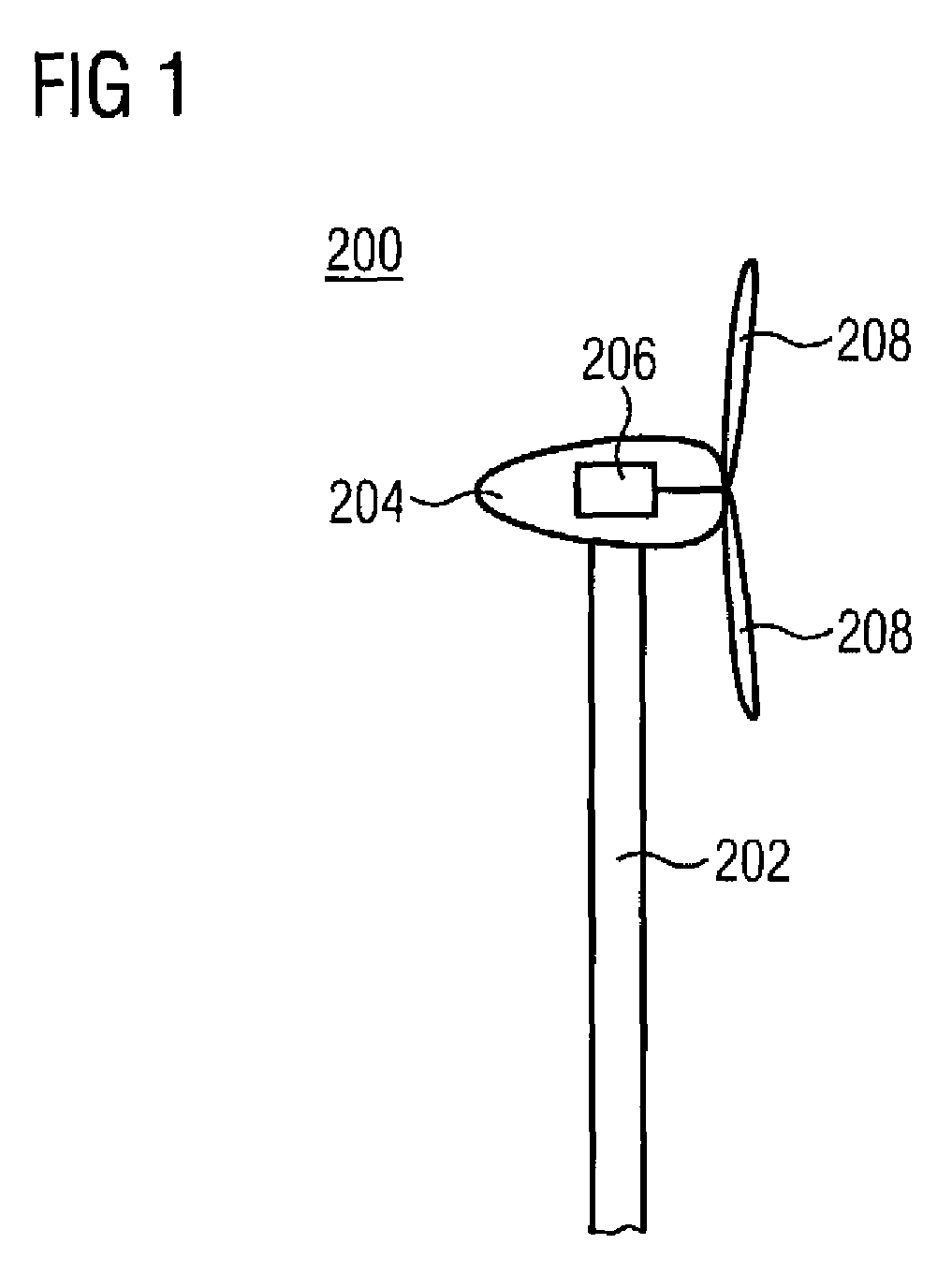
[0091]The illustration in FIG. 1 shows a wind power installation 200. The wind power installation 200 has a mast 202 and a pod 204 which is fitted to this mast. A wind power generator 206 is accommodated in this pod. The wind power generator 206 is connected to blades 208.

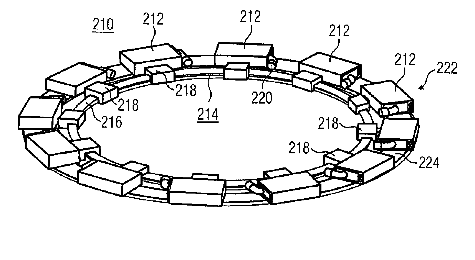
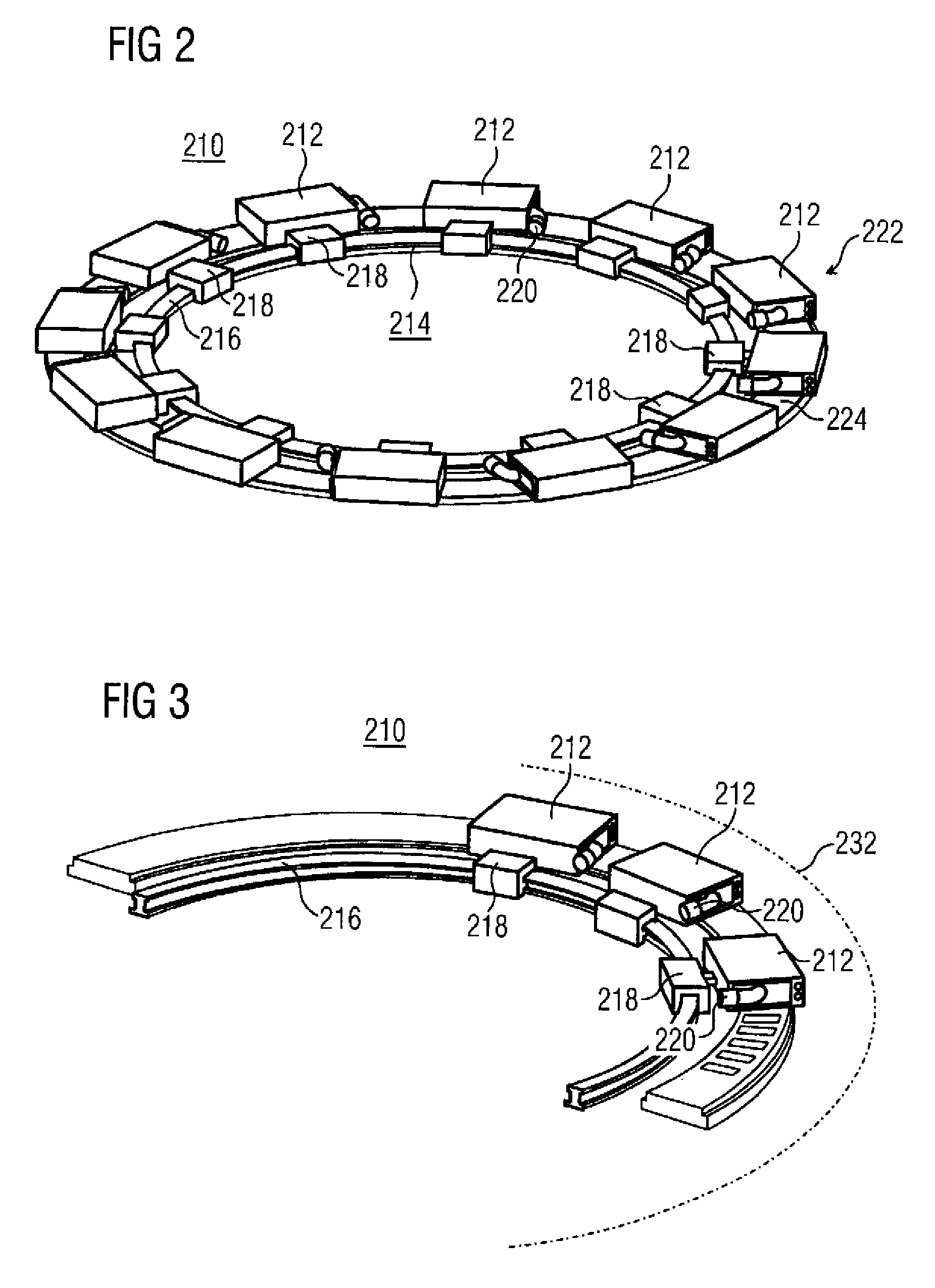
[0092]The illustration in FIG. 2 shows an electrical machine 210 in the form of a disk and with an air gap in the form of a disk. This machine has primary part segments 212. The primary part segments 212 are guided by means of a mounting device 214. The mounting device 214 has a guide rail 216 and slides 218 guided thereon. The slides 218 are mechanically connected to the primary part segments 212. The primary part segments 212 can be separated from one another by spacers which are not illustrated. Each of the primary part segments 212 has its own electrical connection 220. The primary part segments 212 are used to form a primary part 222. The primary part is associated with a secondary part 224. The secondary part...


PUM


Abstract

The invention relates to an electrical machine (1, 2, 210) or its use as a wind power generator and a wind power installation having this electrical machine. The electrical machine has a primary part (3, 4, 222, 212, 213) and a secondary part (5, 6, 224), wherein a disc-like primary part (3, 4, 222, 212, 213) and a disc-like secondary part (5, 6, 224) are provided for forming a disc-shaped air gap, or wherein the electrical machine (1, 2, 210) has a cylindrical primary part (3, 4, 212, 213) and a cylindrical secondary part (5, 6, 224) for forming a cylindrical air gap, wherein a primary part, which can be used for a linear motor, is also used for forming the cylindrical primary part (3, 4, 222, 212, 213).

Description

BACKGROUND OF THE INVENTION[0001]The invention relates to an electrical machine, in particular a generator, with the generator being used in a wind power installation. The electrical machine has a primary part and a secondary part, with both the primary part and the secondary part having a circular contour. The generator which is used in a wind power installation is a wind power generator. Wind power generators are used as mechanical / electrical energy converters in order to obtain energy from wind power. These generators are normally installed at high altitudes. Furthermore, the wind power installation can be used on land, on the coast or else at sea.[0002]At the moment, wind power generators have two major components which can be fitted together or separately, and comprise a stator and a rotor. The two components have a basic cylindrical shape. The wind power generator—referred to as a generator for short—is in this case designed as a unit based on the given and / or expected wind co...

Claims


Application Information

Patent Timeline
IPC IPC(8): H02K21/12H02K41/00
CPCH02K41/033H02K21/24H02K16/04H02K21/44H02K2201/15Y02E10/721H02K2213/12H02K2213/03H02K7/1838Y02E10/72
Inventor HOPPE, THOMASWOLLENBERG, JOHANNES
Owner SIEMENS AG
Learn More