Structural unit

a construction unit and structure technology, applied in the direction of fluid heaters, operating means/releasing devices of valves, light and heating apparatus, etc., can solve the problems of difficulty in handling a spanner at the lower side of the heating facility, misplacement or loss of a spanner, and inability to operate, etc., to achieve adequate free space, simple manner, and large cross section

Inactive Publication Date: 2019-07-04
GRUNDFOS HLDG
View PDF15 Cites 0 Cited by
  • Summary
  • Abstract
  • Description
  • Claims
  • Application Information

AI Technical Summary

Benefits of technology

[0013]Thereby, the tool according to a further development of the invention is provided with a tubular tool head, whose cross-sectional contour corresponds to the cross-sectional contour of the shaft end and which comprises a detent means. Such a tool head has the advantage that it can be applied in a particularly simple manner. After sticking onto the shaft end, this tool head remains on the shaft end by way of the detent means.
[0014]According to an advantageous further development of the invention, the shaft close to its free end is provided with a further positive-fit profile, and specifically preferably on its outer periphery. This positive-fit profile on the outer periphery is advantageously configured as a square profile and seen in the direction to the free shaft end is arranged in front of the positive-fit profile for the tool belonging to the construction unit, thus for example in front of the hexagon profile head on the shaft end. A hexagon profile can alternatively also be provided here. Such an arrangement has the advantage that with this, the shaft also has a profile, as is counted as belonging to the state of the art and which can be actuated with a common jaw tool (spanner tool). This profile is typically envisaged for use by the service installation technician. This profile advantageously has a larger cross section than the subsequent profile at the shaft end, said subsequent profile being engaged with the tool of the construction unit. By way of this, one succeeds in a larger moment than is possible with the tool belonging to the construction unit, being able to be applied, by way of attaching a jaw tool to this profile. This is a safeguard aspect, by which means it is ensured that the end-user cannot overtighten the shaft, but only the expert, who whoever knows which force must and is permitted to be applied with a suitable tool, without damage to the shaft or the valve occurring. This aspect is particularly important if the shaft has seized due to lack of actuation.
[0015]The tool belonging to the construction unit is advantageously configured such that it comprises a tool head which is envisaged for the engaging over the profiled shaft end in a locking manner, which is to say by detent, as well as a tool grip which is envisaged for being gripped around by the hand. These two tool parts are connected by a tool shank which creates the necessary distance, so that adequate free space is given for the manual actuation, without the danger of injury on a covering part or likewise, which for example has sharp edges. The tool head and the tool grip are arranged at ends of the shank which are away from one another and thus largely rule out any faulty operation.
[0016]Such a tool can advantageously be configured as a single-piece plastic component which is preferably fiber-reinforced, so that the necessary forces can also be reliably transmitted.
[0017]If the tool is configured as a plastic injection molded part, which is advantageous, then this on the one hand can be inexpensively manufactured, and on the other hand the spring tongue or spring tongues as well as the tool head can be configured such that they can be manufactured with a simple tool without lost cores, differently than would conversely be the case at the shaft end.

Problems solved by technology

However, in practice it has been found that the handling of a spanner at the lower side of the heating facility is often quite difficult for the novice or layman, and on the other hand that the spanner is misplaced or lost and the operation then no longer possible.

Method used


Image

  • Structural unit
  • Structural unit
  • Structural unit

Examples


Embodiment Construction

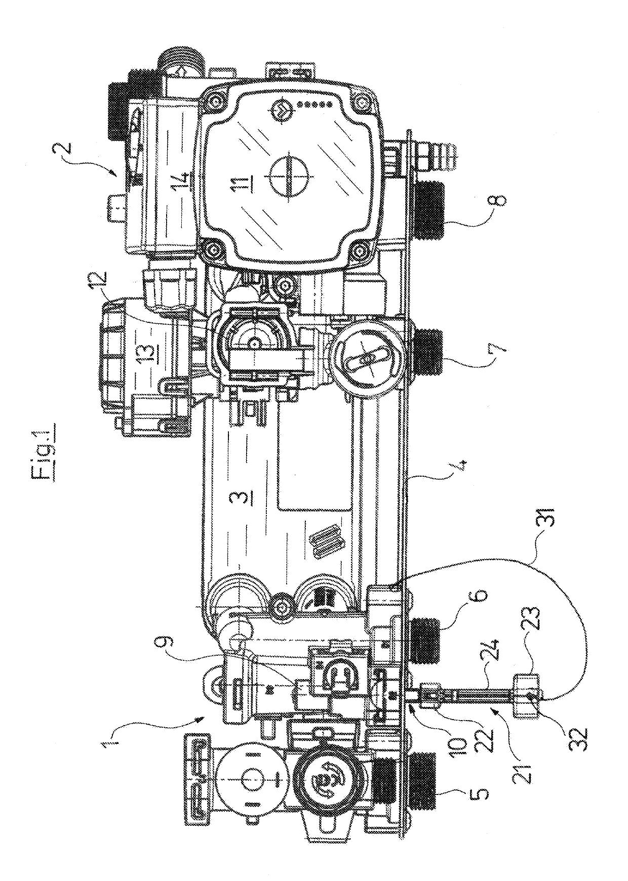
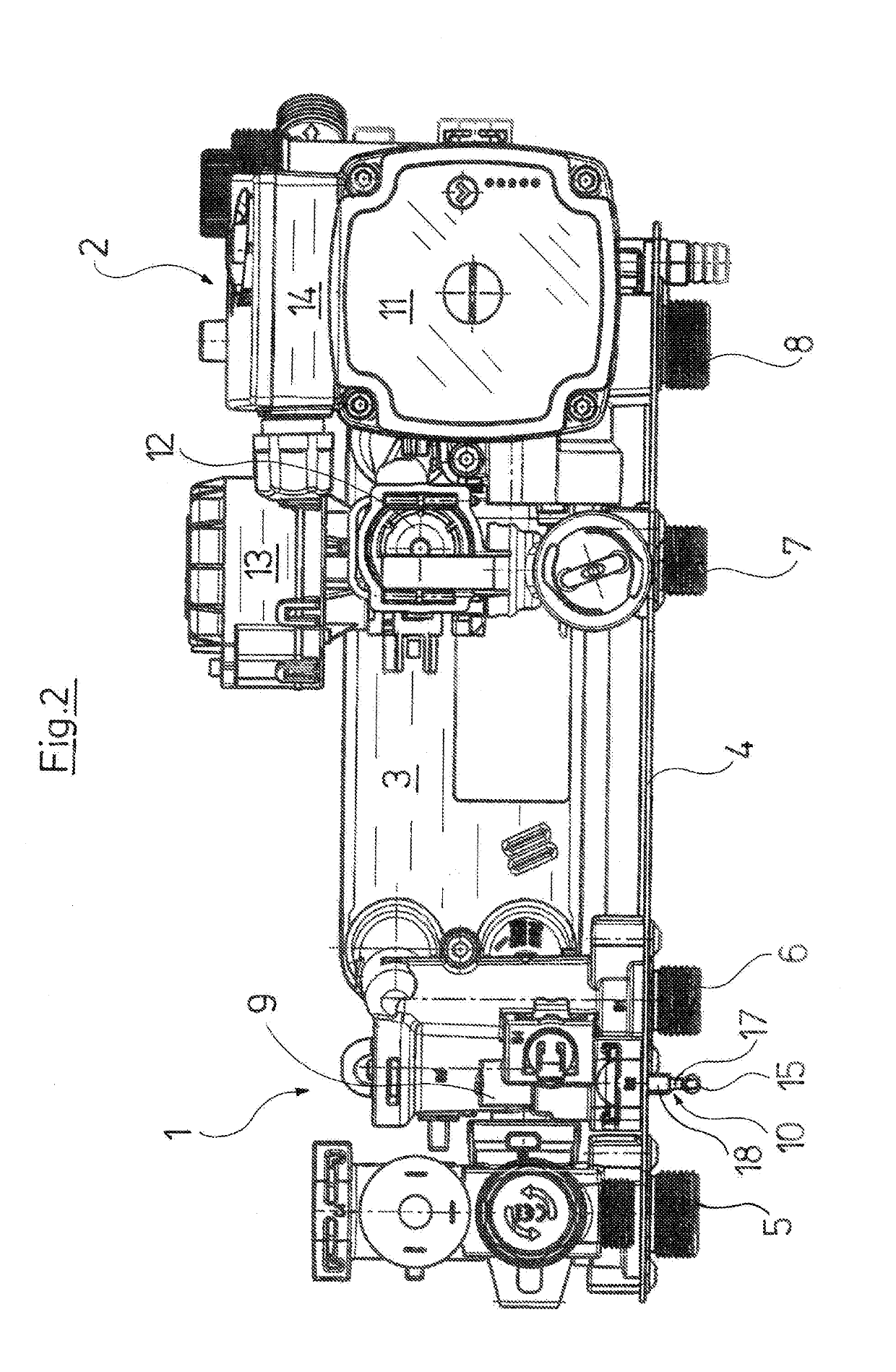
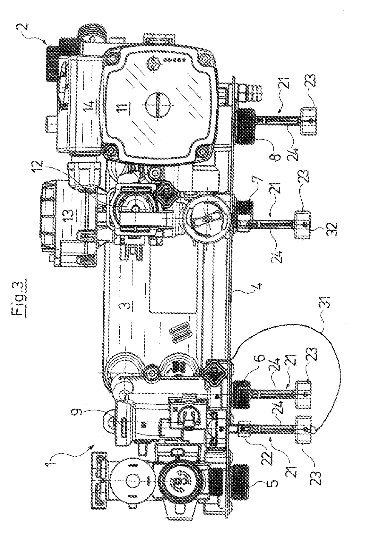
[0033]Referring to the drawings, with the construction unit which is represented in FIG. 1-3, it is the case of a construction unit of a compact heating facility, specifically of a gas heater, which with regard to basic construction aspects is described for example in EP 2 093 516 B 1, which is referred to inasmuch as this is concerned (the entire contents of EP 2 093 516 B1 are incorporated herein by reference). The construction unit is comprised of two part-construction-units 1 and 2 which are hydraulically and mechanically connected to one another by a plate heat exchanger 3. The construction unit is received by a plate 4 which runs approximately horizontally in the installed condition and which forms part of the part of the chassis of the compact heating facility, said facility being fastened to a wall at the rear side and with which facility the four conduit connections 5, 6, 7, 8 of the part-construction-units 1 and 2 are led out at the lower side. These conduit connections 5-...


PUM


Abstract

A construction unit (1, 2) forms part of a gas heater and includes a valve (9) which is actuatable by way of a stem (10). The stem (10) includes positive-fit device. The stem (10) is controllable from the outside via a tool which can be brought into engagement with the positive fit device. A detent engagement device (18, 27) holds the tool (21) in engagement with the stem (10), so that the valve is controllable without the aid of outside tools.

Description

CROSS REFERENCE TO RELATED APPLICATIONS[0001]This application is a United States National Phase Application of International Application PCT / EP2017 / 064384, filed Jun. 13, 2017, and claims the benefit of priority under 35 U.S.C. § 119 of European Application 16176865.0, filed Jun. 29, 2016, the entire contents of which are incorporated herein by reference.TECHNICAL FIELD[0002]The invention relates to a construction unit for a compact heating facility, with at least one valve which is controllable by hand by way of a shaft and whose shaft comprises positive-fit means at the end side, which is to say at the end, wherein the shaft can be controlled from the outside by way of a tool which is engaged with the positive fit means.BACKGROUND[0003]Such construction units are nowadays counted as belonging to the state of the art in various variations. They serve for the supply of the room heating with warm water and / or additionally for the production of warm service water. They are typically p...

Claims


Application Information

Patent Timeline
Patent Type & Authority Applications(United States)
IPC IPC(8): F16K31/60F16K5/04F24H9/20
CPCF16K31/602F16K5/0442F24H9/2007F24H9/06F16C11/103Y10T137/7065F16K35/04F16K31/605F16K35/02F16K35/06F16K31/60F16C11/106F16K35/027F16C11/10Y10T137/6021Y10T137/6024Y10T74/20762
Inventor HANSEN, OLEJENSEN, SOREN SOGAARD
Owner GRUNDFOS HLDG
Why Eureka
Try Eureka