Cryopump hybrid frontal array

Active Publication Date: 2017-01-12
EDWARDS VACUUM LLC
View PDF5 Cites 4 Cited by
  • Summary
  • Abstract
  • Description
  • Claims
  • Application Information

AI Technical Summary

Benefits of technology

[0014]A hybrid frontal array allows for pumping speeds approximating those of a louver array but with the flow control of an orifice plate. Like louvered arrays, the hybrid design produces a large ratio of gas particle transmission

Problems solved by technology

However, orifice plates severely restrict Type II and Type III gases to the second stage

Method used


Image

  • Cryopump hybrid frontal array
  • Cryopump hybrid frontal array
  • Cryopump hybrid frontal array

Examples


Embodiment Construction

[0048]A description of example embodiments of the invention follows.

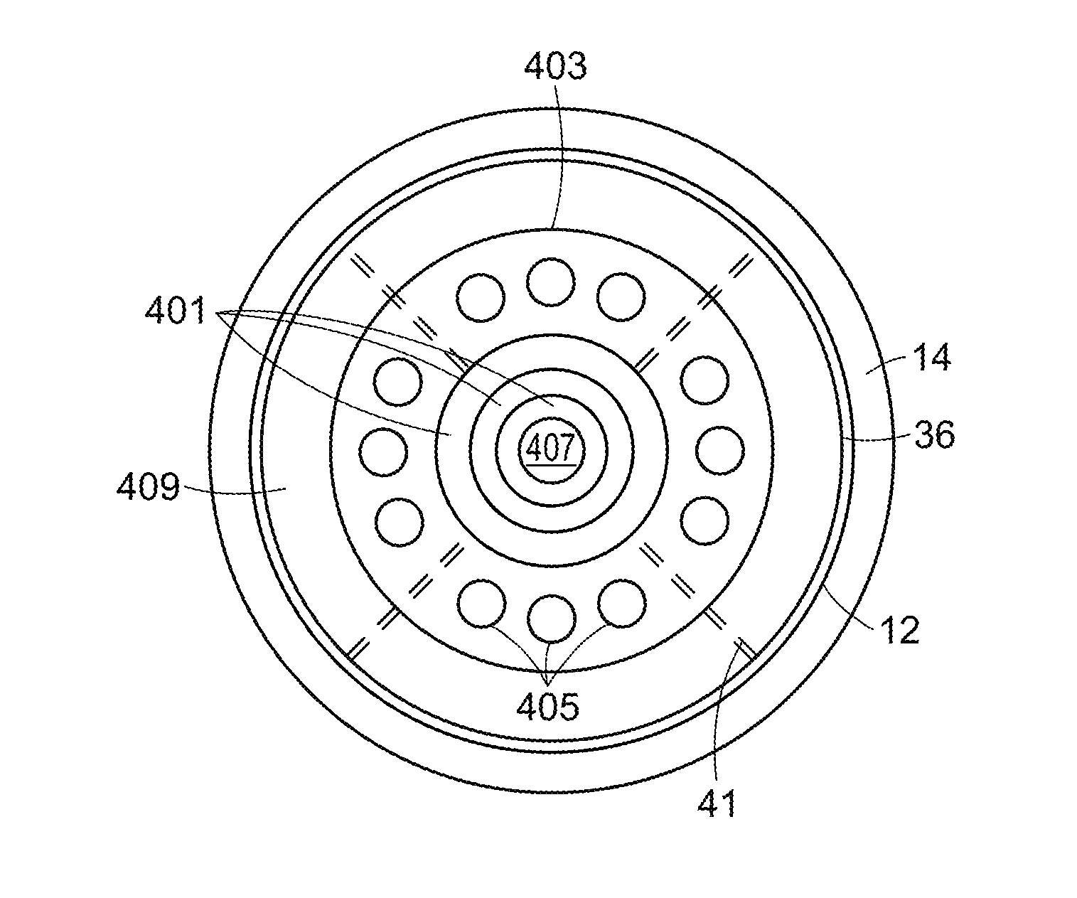
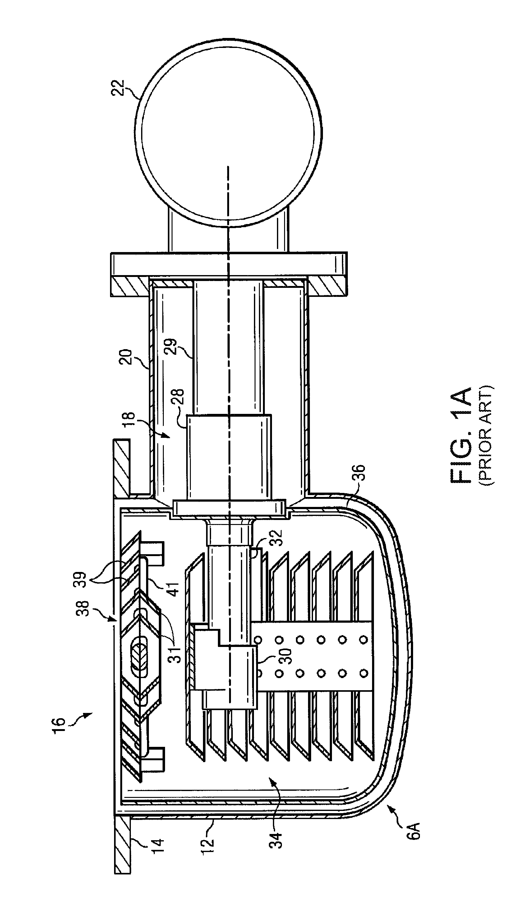
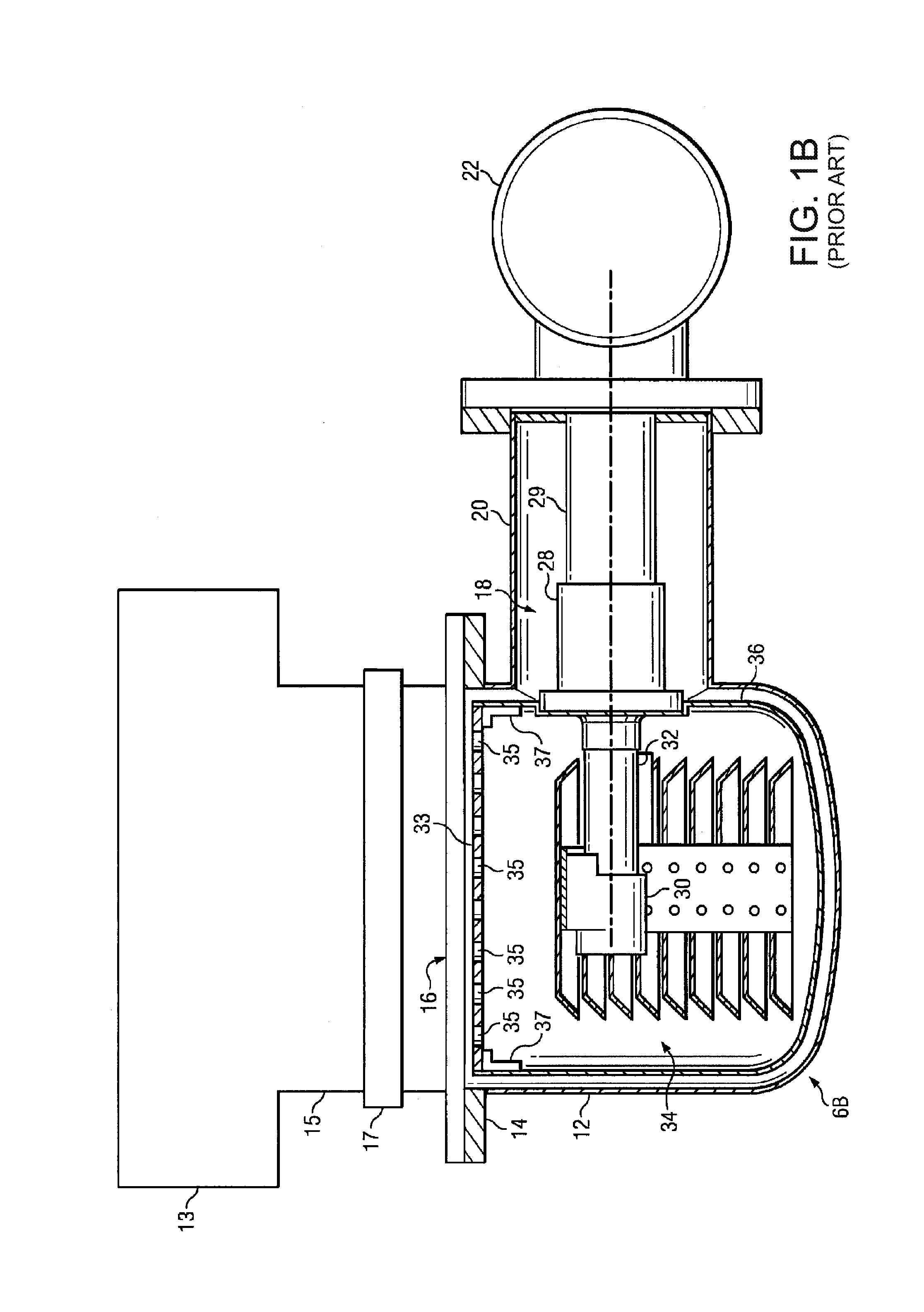
[0049]Cross-section side views of prior art circular cryopumps 6A and 6B attached to a process chamber 13 are shown in FIGS. 1A and 1B, respectively. Each cryopump 6A and 6B includes a cryopump housing 12 which may be mounted either directly to the process chamber along flange 14 or to an intermediate gate valve 17 between it and the process conduit 15 which is connected to the process chamber 13. The conduit 15 includes a gate valve 17 which may be employed to isolate the cryopump 6 from the process chamber 13. The cryopumps 6A and 6B are capable of pumping the process chamber 13. The cryopumps 6A and 6B include a cryopump housing 12 bolted to conduit 15, which is coupled to the process chamber 13. The front opening 16 in the cryopump housing 12 communicates with the circular opening in the process chamber 13. A two stage cold finger 18 of a refrigerator protrudes into the cryopump housing 12 through a cylindrical ...


PUM


Abstract

A cryopump comprises a refrigerator, a condensing array cooled by the refrigerator, a radiation shield surrounding the condensing array and cooled by the refrigerator. The radiation shield has a frontal opening covered by a frontal array that is also cooled by the refrigerator. The frontal array comprises louvers across an otherwise substantially open center region of the frontal opening and an orifice plate across an outer region of the frontal opening. The hybrid frontal array allows for pumping speeds approximating those of a louver frontal array but with flow control comparable to an orifice plate.

Description

RELATED APPLICATIONS[0001]This application is a continuation of International Application No. PCT / US2015 / 021571, which designated the United States and was filed on Mar. 19, 2015, published in English, which claims the benefit of U.S. Provisional Application No. 61 / 971,973, filed on Mar. 28, 2014, and U.S. Provisional Application No. 61 / 969,029, filed on Mar. 21, 2014. The entire teachings of the above applications are incorporated herein by reference.BACKGROUND OF THE INVENTION[0002]Cryopumps currently available, whether cooled by open or closed cryogenic cycles, generally follow the same design concept. A low temperature second stage cryopanel array, usually operating in the range of 4-25 K, is a primary pumping surface. This surface is surrounded by a high temperature radiation shield usually operated in the temperature range of 40-130 K, which provides radiation shielding to the lower temperature array. The radiation shield generally comprises a housing which is closed except at...

Claims


Application Information

Patent Timeline
IPC IPC(8): F04B37/08F04B53/16
CPCF04B53/16F04B37/08Y10S417/901F25D19/006F25B9/14
Inventor WELLS, JEFFREY A
Owner EDWARDS VACUUM LLC
Why Eureka
Try Eureka