Polymer coated optical fiber

Active Publication Date: 2017-01-12
SONORO
View PDF5 Cites 7 Cited by
  • Summary
  • Abstract
  • Description
  • Claims
  • Application Information

AI Technical Summary

Benefits of technology

The present invention relates to polymer coated optical fibers and sensor systems comprising same. The invention describes a coated optical fiber with improved sensitivity and a polymeric coating that has a specific range of values for its Poisson's Ratio and shear modulus. The invention also includes an acoustic sensor system comprising these coated optical fibers. The invention further provides a method for producing the coated optical fibers, a system for detecting acoustic changes in a channel, and a system for detecting acoustic changes in a channel with an interrogator and signal processing device. The technical effect of this invention is to enhance the sensitivity and accuracy of optical fiber sensor systems for detecting changes in acoustic environments.

Problems solved by technology

AIP coatings, however, include air bubbles that collapse as operating pressures increase which significantly reduces the sensitivity enhancement.
AIP coatings, therefore, are not suitable for high pressure applications.
Commercially available electrical downhole sensor systems (without use of cooling or temperature isolation devices) are limited to use in downhole applications at temperatures of 110° C. or below.

Method used


Image

  • Polymer coated optical fiber
  • Polymer coated optical fiber
  • Polymer coated optical fiber

Examples


example 1

Preparation of Coated Fibers

[0094]The following coated fibers were prepared. The fibers were all commercially available glass / fused silica quartz fibers.[0095]80 um glass fiber with acrylate coating and Hytrel® 3078 buffering to 1500 um.[0096]80 um glass fiber with high temperature acrylate coating and Hytrel® 3078 buffering to 1500 um.[0097]125 um glass fiber with acrylate coating and Hytrel® 3078 buffering to 1500 um.[0098]125 um glass fiber with high temperature acrylate coating and Hytrel® 3078 buffering to 1500 um.[0099]80 um glass fiber with acrylate coating and SE9058 buffering to 1500 um.[0100]80 um glass fiber with high temperature acrylate coating and SE9058 buffering to 1500 um.[0101]125 um glass fiber with acrylate coating and SE9058 buffering to 1500 um.[0102]125 um glass fiber with high temperature acrylate coating and SE9058 buffering to 1500 um.[0103]Both 80 um and 125 um glass fibers with acrylate, high temperature acrylate or polyimide coatings all with FBGs pre-wr...

example 2

Testing of Coated Fibers

[0109]The Hytrel® and Radcure polymer coated fibers were each tested for acoustic sensitivity in a static calibration chamber. As the coating enhances both the static and dynamic strain in the cladded core of the optical fiber, the use of a static calibration test can greatly simplify obtaining a calibration of the acoustic sensitivity (commonly called Sensor Scale Factor). Accordingly, measuring the change in the fiber strain in a relatively simple static pressure chamber avoids the complexity and higher costs of conducting an acoustic sensor calibration in an anechoic chamber.

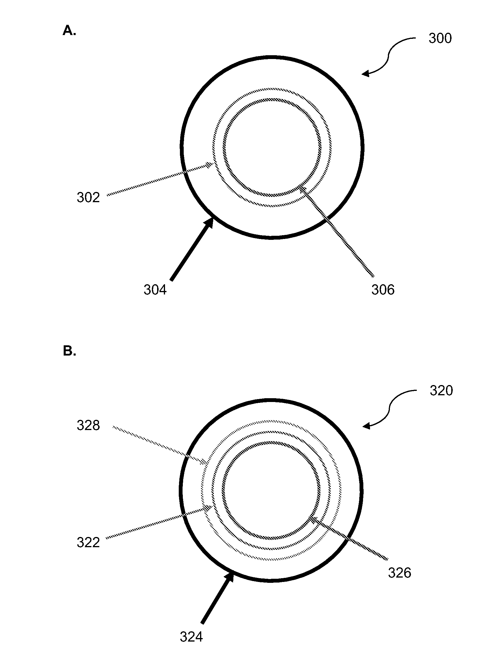
[0110]Briefly, the test chamber was constructed to accept wound optical fiber over a rigid mandrel to create a sensor. The chamber included a controlled water inlet and a controlled water outlet, such that water flow into and out of the chamber could be regulated allowing the creation of a balanced pressure within the chamber. Water flow through the system maintained the water temperat...


PUM

PropertyMeasurementUnit
Temperatureaaaaaaaaaa
Diameteraaaaaaaaaa

Abstract

Coated optical fibers and uses of such fibers as sensors in high temperature and / or high pressure environments. The coated optical fiber has improved sensing properties at elevated pressure and / or temperature, such as enhanced acoustic sensitivity and / or a reduced loss in acoustic sensitivity. The use of the coated optical fibers in various sensing applications that require operation under elevated pressure and / or temperature, such as, acoustic sensors for various geological, security, military, aerospace, marine, and oil and gas applications are also provided.

Description

FIELD OF THE INVENTION[0001]The present invention relates to the field of fiber optics and, in particular, to a polymer coated optical fiber suitable for use as a sensor in high temperature and / or high pressure operating conditions.BACKGROUND OF THE INVENTION[0002]Optical fibers find widespread use in acoustic sensors (Kirkendall & Dandridge, 2004, J Phys. D: Appl. Phys. 37:R197-R216). Polymeric coatings over optical fibers are known to increase the acoustic sensitivity of the fiber (Hughes & Jarzynski, 1980, Applied Optics, 19(1):98-107; Giallorenzi et al., 1982, IEEE J Quantum Engineering, QE18, pp 626-665). Further enhancement of sensitivity has been demonstrated through the use of air-included polymer (AIP) coatings (Cole et al., 2002, 15thOptical Fiber Sensors Conf. (Portland Oreg.) vol 15 IEEE Catalog 02EX533). AIP coatings, however, include air bubbles that collapse as operating pressures increase which significantly reduces the sensitivity enhancement. AIP coatings, therefor...

Claims


Application Information

Patent Timeline
IPC IPC(8): G02B6/02C03C25/32C03C25/28G01H9/00C03C25/10
CPCG02B6/02395G02B6/02033G01H9/004C03C25/18C03C25/106C03C25/285C03C25/323G02B6/02076C03C25/1065C03C25/26C03C25/326G02B1/048
Inventor RACOSKY, MICHAELBRIGGS, WILLIAMDEMETZ, FREDHULL, JOHNJALILIAN, SEYED EHSAN
Owner SONORO
Why Eureka
Try Eureka