Method of computing an estimated queuing delay

Inactive Publication Date: 2017-01-12
LASNE HAIDER MR +1
View PDF2 Cites 13 Cited by
  • Summary
  • Abstract
  • Description
  • Claims
  • Application Information

AI Technical Summary

Benefits of technology

[0025]continuous queue profile time windows may be dynamically merged or split to consolidate historical data while

Problems solved by technology

As industrial and commercial processes become increasingly automated, autonomous and distributed, the optimization of the delivery of services becomes increasingly complex.
In some case logistical delay may include more delay components than just transit time delay.
Prior art typically does not consider alternative locations, or alternative services.
Thus, prior art is not able to estimate queue delays for a new service locations.
In particular, prior art does not use clust

Method used


Image

  • Method of computing an estimated queuing delay
  • Method of computing an estimated queuing delay
  • Method of computing an estimated queuing delay

Examples


Embodiment Construction

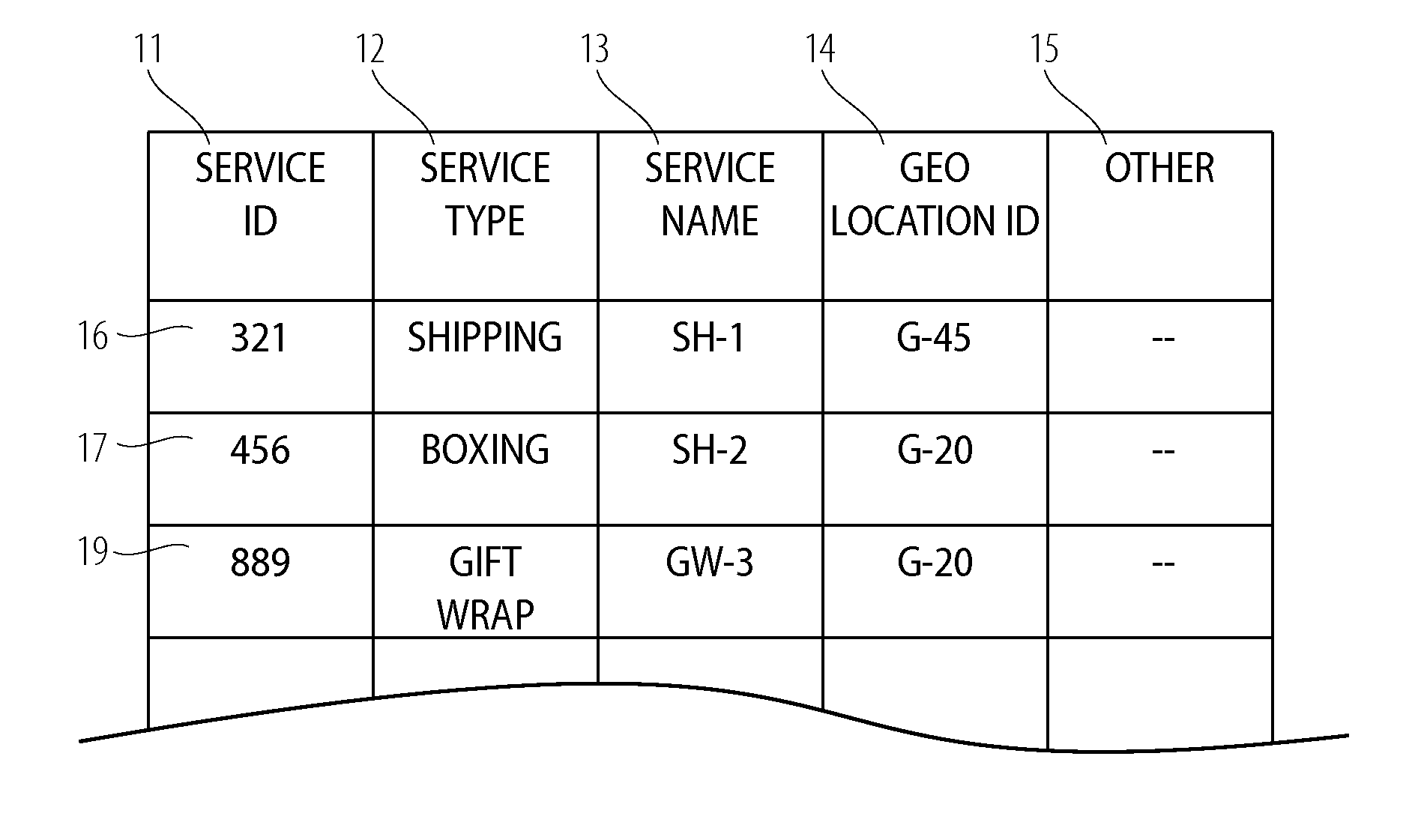
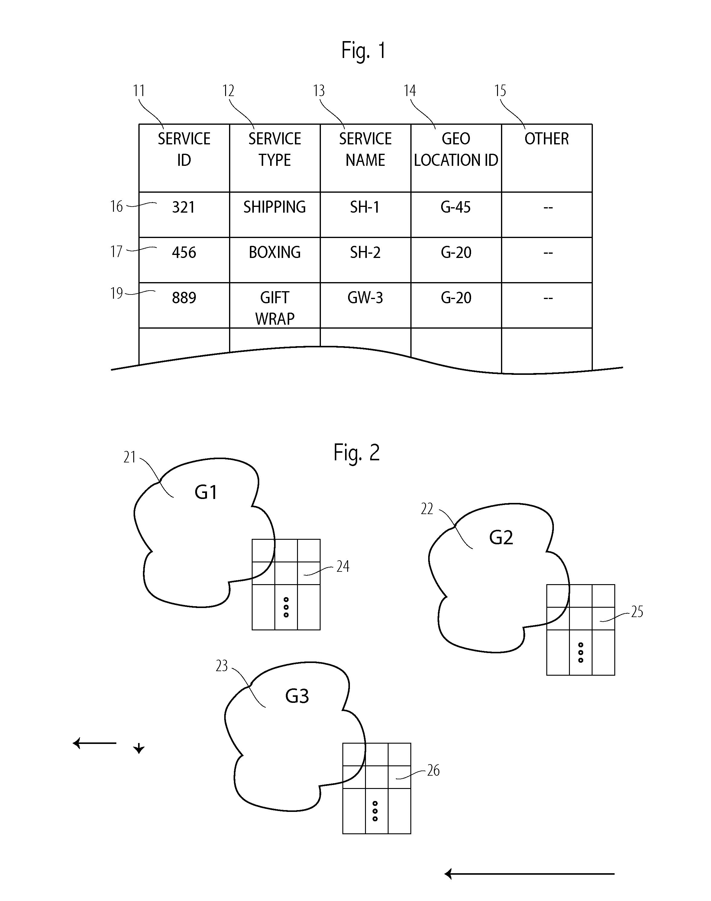
[0129]Turning now to FIG. 1, we see a portion of a simplified geographic service point table with three service points shown. Typically, there is one such table for each geographic region. For example, this table might be for geographic region G1, shown as 21 in FIG. 2. The columns in the table are 11 through 15. The three service points shown are in rows are 16, 17, and 18. The service ID, 11, is a unique identifier for the service point in that row. Each service point, shown as one row, is one location that is able to deliver one type of service. Column 12 shows the service type for each service point. For example, service point 321 in row 16 has a service type of “shipping.” Column 13 shows the service name for each service point. For example, service point 456 in row 17 has a service name of SH-2. The service name is not strictly required, and is typically for convenience and for reference to some other naming system. That is, the service ID is typically used within an embodimen...


PUM


Abstract

A method of computing an estimated queuing delay is described that uses both historical queue delay data in the form of multiple calendar-based queue delay profiles and real-time data in the form of field-reports from service objects of actual queue delay. A decision selects either the source data from queue delay profiles or a real-time report. A clustering algorithm is used to assign potentially widely disparate geographic locations to clusters and to assign service type records to a cluster. Calendar-based queue delay profiles may be associated at the cluster level, at the service-type level, and at the individual service point level. Service objects may request an estimated queue delay; service objects may be provided with a estimated queue delay for a specified service point and also delays for alternative service points. Such requests may be prior to selecting or moving to a particular service queue.

Description

BACKGROUND OF THE INVENTION[0001]As industrial and commercial processes become increasingly automated, autonomous and distributed, the optimization of the delivery of services becomes increasingly complex. The field of this invention is estimating queuing time delays for objects requiring services when there are multiple options for both the types of services and location of those services. In particular, one purpose and field of this invention is to generate an estimated queue delay for a particular service type at a particular location.[0002]Queuing delays most generally may be broken into three components: (1) travel time or logistics time to get to the start of the queue; (2) waiting time in the queue, from the start of the queue to the end of the queue; (3) service time. In this invention we focus on estimating: (2) the waiting time in the queue, from the start of the queue to the end of the queue. However, the logistics delay to get to the start of the queue is an important co...

Claims


Application Information

Patent Timeline
IPC IPC(8): G06Q10/06
CPCG06Q10/063114
Inventor MANTRI, MILIND S.LASNE, HAIDER JAINUDDIN
Owner LASNE HAIDER MR
Why Eureka
Try Eureka