Robot apparatus, and measuring method of rotation driving apparatus
- Summary
- Abstract
- Description
- Claims
- Application Information
AI Technical Summary
Benefits of technology
Problems solved by technology
Method used
Image

Examples
first embodiment
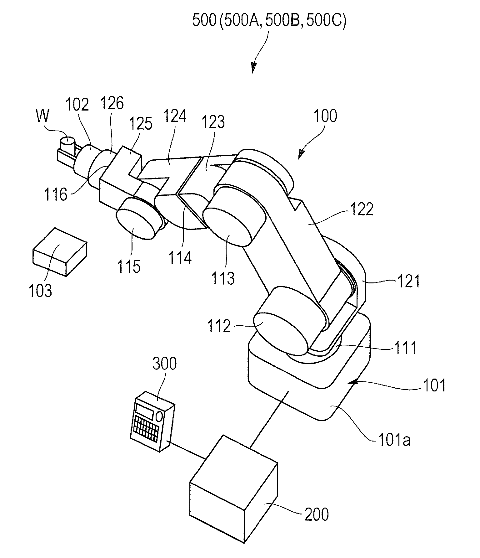
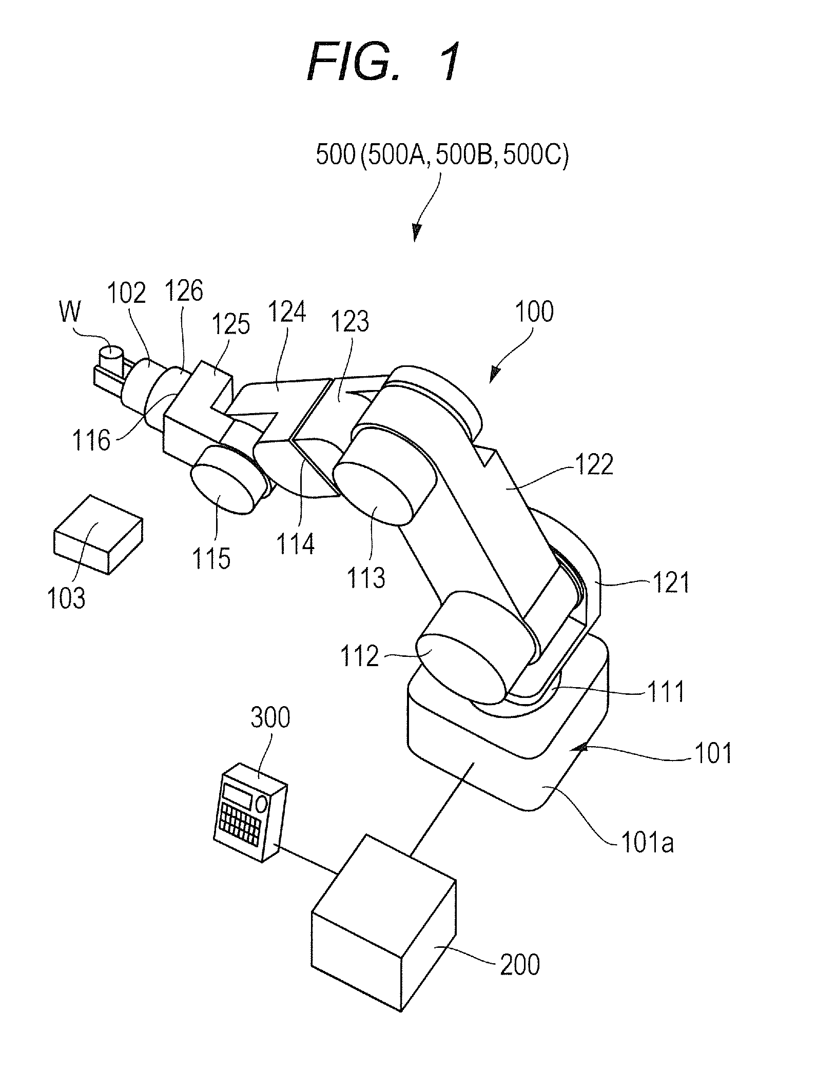
[0040]A robot apparatus 500 according to the first embodiment of the present invention will be described with reference to FIGS. 1 to 8. First, the entire constitution of the robot apparatus 500 according to the first embodiment will be described with reference to FIGS. 1 to 3. Namely, FIG. 1 is the perspective diagram for schematically illustrating the robot apparatus 500 according to the first embodiment, FIG. 2 is the cross-section diagram for illustrating one cross-section constitution of the joint of a robot arm 100 illustrated in FIG. 1, and FIG. 3 is the block diagram for illustrating the constitution of a controlling apparatus 200 of the robot apparatus 500 according to the present embodiment.
[0041]As illustrated in FIG. 1, the robot apparatus 500 comprises the robot arm 100 which performs assembly with a work W, the controlling apparatus 200 which controls the robot arm 100, and a teaching pendant 300 which serves as an operation terminal.
[0042]The robot arm 100 comprises, ...
second embodiment
[0091]Subsequently, the robot apparatus according to the second embodiment of the present invention will be described with reference to FIGS. 9 to 12B. Although the entire constitution of the robot apparatus is the same as that illustrated in FIG. 1, a reference symbol 500A of FIG. 1 is used as to the robot apparatus according to the second embodiment as a matter of convenience.
[0092]In the above first embodiment, the constitutions for performing the lost motion measurement and the lifetime diagnosis have been described for, by way of example, the joint 111 in which the mass of the driven part of the joint to which the lost motion measurement is performed does not act as the gravity moment around the joint axis thereof. That is, in the first embodiment, sine the joint axis of the joint 111 approximately coincides with the vertical direction, the rotation moment (gravity moment) generated by the mass of the driven part at the hand-end side of the joint 111 does not act around this jo...
third embodiment
[0118]Subsequently, lost motion measurement control according to the third embodiment of the present invention will be described with reference to FIGS. 13 and 14. A reference symbol 500B of FIG. 1 is used as for the robot apparatus according to the present embodiment. As well as the second embodiment, it is assumed that the hardware constitution and the software configuration in the present embodiment are the same as those described in the first embodiment.
[0119]In the second embodiment, the condition of the gravity moment acting around the joint axis of the measurement-target joint is controlled by controlling the orientation of the driven part at the hand-end side of the measurement-target joint. In particular, the condition is controlled such that the gravity moment MgL2 generated by the driven part is smaller than the frictional torque Tf.
[0120]However, it is not always possible to perform the orientation control of the driven part as described with reference to FIGS. 11A to 12...
PUM
 Abstract
Description
Claims
Application Information
 - R&D
- Intellectual Property
- Life Sciences
- Materials
- Tech Scout
- Unparalleled Data Quality
- Higher Quality Content
- 60% Fewer Hallucinations
Browse by: Latest US Patents, China's latest patents, Technical Efficacy Thesaurus, Application Domain, Technology Topic, Popular Technical Reports.
© 2025 PatSnap. All rights reserved.Legal|Privacy policy|Modern Slavery Act Transparency Statement|Sitemap|About US| Contact US: help@patsnap.com