Video display system, video display device, and video display method

a video display system and video display technology, applied in the field of video display systems, can solve the problems of non-uniform luminosity of the captured video image, inability to clearly display the video image, and inability to improve so as to achieve the effect of improving the dynamic range upon capturing and improving the visibility of the video imag

Active Publication Date: 2017-01-19
PANASONIC INTELLECTUAL PROPERTY MANAGEMENT CO LTD
View PDF3 Cites 13 Cited by
  • Summary
  • Abstract
  • Description
  • Claims
  • Application Information

AI Technical Summary

Benefits of technology

[0014]According to the present disclosure, when a video image captured by an omnidirectional camera is seen by using a head mounted display, the luminosity of the video image is dynamically adjusted in accordance with the direction of the video display device. Thus, a dynamic range upon capturing can be increased in a pseudo manner, and the visibility of the video image can be improved.

Problems solved by technology

In the outdoor environment, however, a video image captured in the same direction as sunlight and a video image captured in the opposite direction to sunlight coexist in a 360-degree range video image, and the luminosity of the captured video image is rendered non-uniform according to an azimuth.
However, in a case where a user sees the video image captured by the omnidirectional camera using the head mounted type display (for example, a head mounted display; HMD), the video image is not clearly displayed even if a dark video image such as a video image captured in the opposite direction to sunlight is illuminated by a backlight.
Thus, if the luminosity of the video image is different according to a direction in which the user watches, illuminating the video image uniformly at the same luminosity does not improve the visibility of the video image.

Method used


Image

  • Video display system, video display device, and video display method
  • Video display system, video display device, and video display method
  • Video display system, video display device, and video display method

Examples


Embodiment Construction

[0027]Hereinafter, an embodiment (hereinafter, referred to as the present embodiment) in which a video display system, a video display device, and a video display method according to the present disclosure are specifically disclosed will be described in detail with appropriate reference to the drawings. However, excessively detailed descriptions may not be provided. For example, detailed descriptions of previously well-known matters and duplicate descriptions of substantially the same configurations may not be provided. The purpose of this is to avoid the following descriptions becoming unnecessarily redundant and to facilitate understanding thereof for those skilled in the art. The appended drawings and the following descriptions are provided in order to allow those skilled in the art to sufficiently understand the present disclosure and are not intended to limit the subject matter disclosed in the claims.

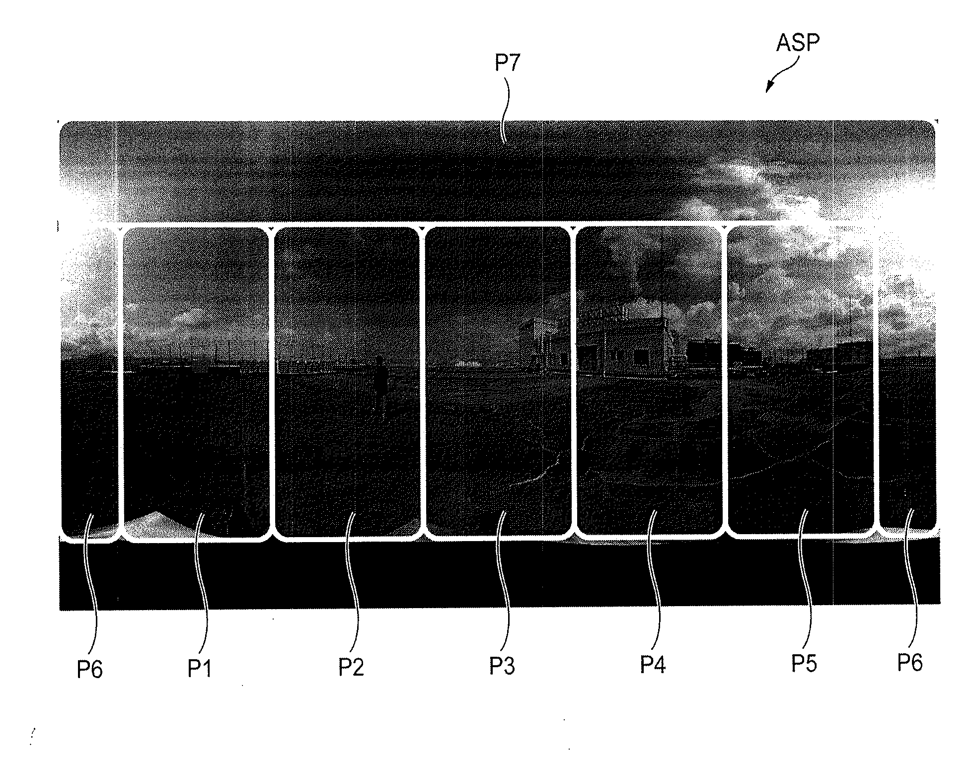
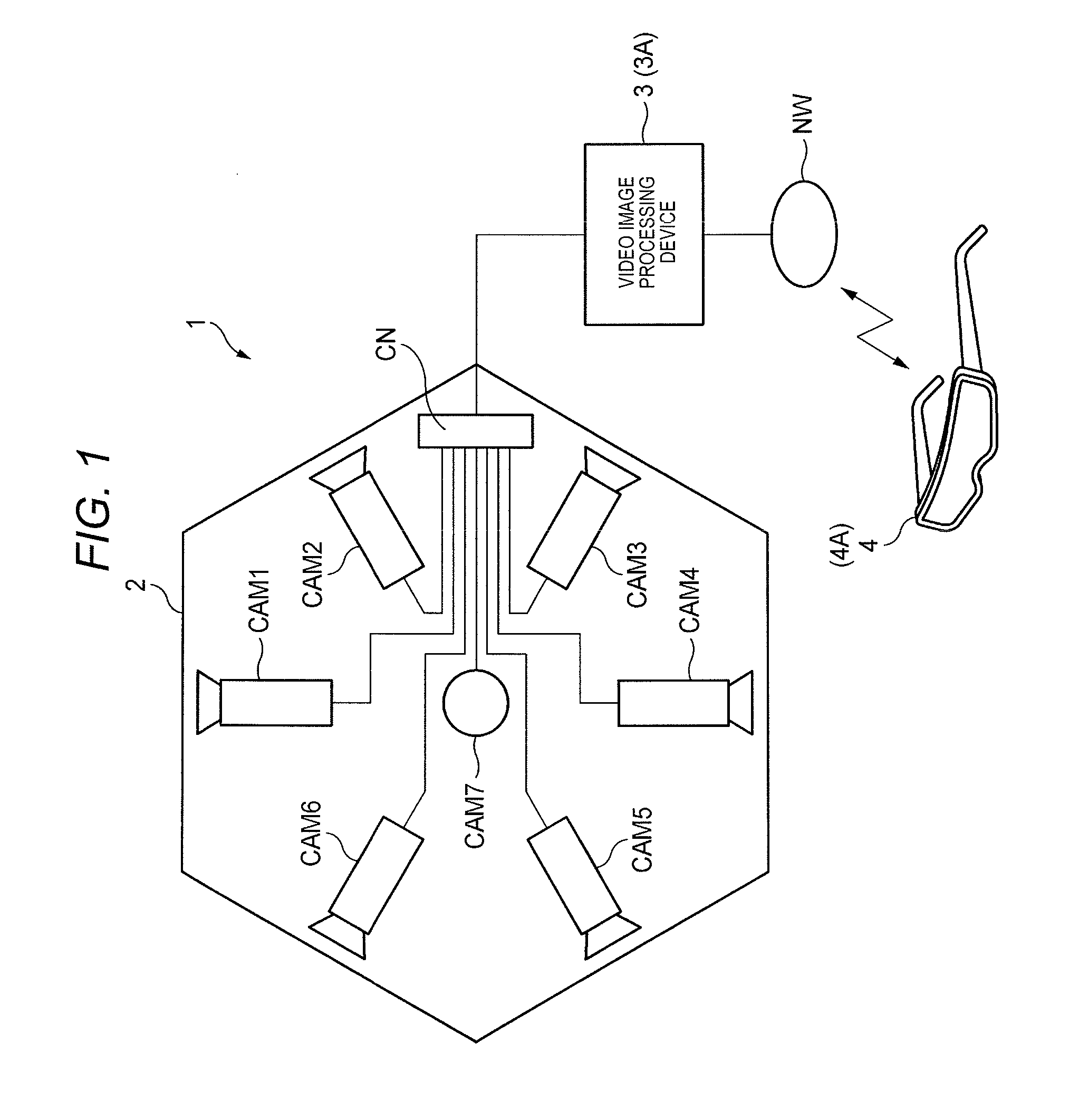
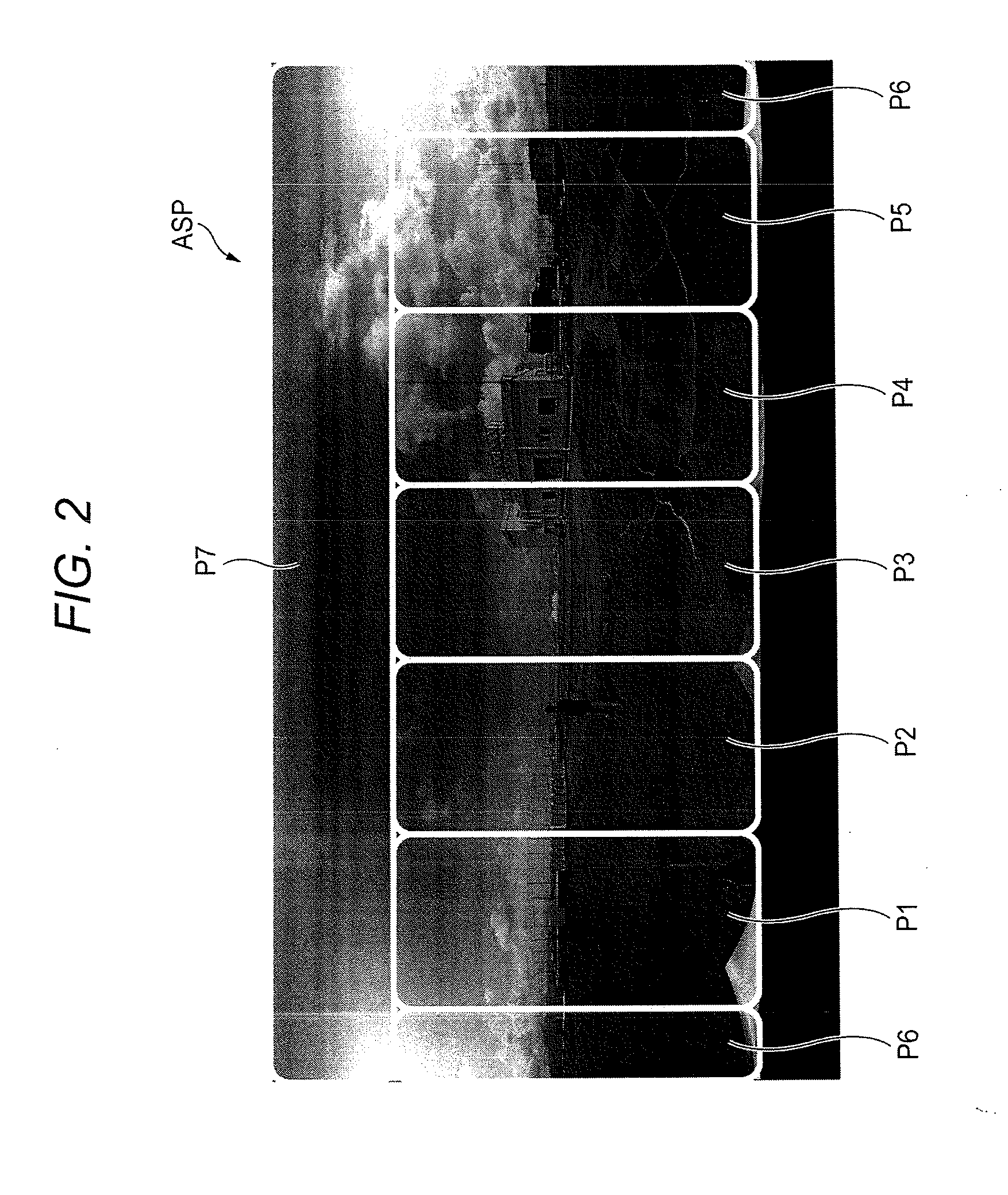
[0028]Omnidirectional camera system 1, as an example of a video display syste...


PUM


Abstract

A video image processing device uses a plurality of video data captured by a plurality of cameras to generate a wide range video data of the entire celestial sphere having a 360-degree range around an area where the plurality of cameras is installed and to transmit the generated wide range video data of the entire celestial sphere to a video display device. The video display device detects a direction of the video display device as a direction of a sight line of the user, receives the transmitted wide range video data of the entire celestial sphere, segments a predetermined area of video data including a detection result of a sensor from the wide range video data of the entire celestial sphere, adjusts a luminosity of the extracted predetermined area of video data to fall in a certain range of luminosity, and displays the adjusted predetermined area of video data.

Description

BACKGROUND[0001]1. Technical Field[0002]The present disclosure relates to a video display system, a video display device, and a video display method for displaying video data that is captured from directions in the entire celestial sphere.[0003]2. Description of the Related Art[0004]A camera (hereinafter, referred to as an omnidirectional camera) that can capture a video image from directions in the entire celestial sphere (that is, in the 360-degree range) has started to emerge in recent years. Since the omnidirectional camera can capture a wide range video image, capturing is mostly performed in an outdoor environment considering the assumed use thereof. In the outdoor environment, however, a video image captured in the same direction as sunlight and a video image captured in the opposite direction to sunlight coexist in a 360-degree range video image, and the luminosity of the captured video image is rendered non-uniform according to an azimuth. Thus, an approach to increase the ...

Claims


Application Information

Patent Timeline
Patent Type & Authority Applications(United States)
IPC IPC(8): G09G3/20H04N5/247G06F1/16
CPCG09G3/2003H04N5/247G06F1/163G06F3/147H04N23/45H04N23/698H04N23/90
Inventor OGINO, RYOJIKUWADA, JUNYAMAKINO, HIROYASU
Owner PANASONIC INTELLECTUAL PROPERTY MANAGEMENT CO LTD
Why Eureka
Try Eureka