Massive MIMO array emulation

a technology of mass mimo arrays and arrays, applied in the field of mass mimo array emulation, can solve the problem of becoming computationally prohibitive for mass mimo arrays

Active Publication Date: 2017-01-19
SPIRENT COMM
View PDF6 Cites 27 Cited by
  • Summary
  • Abstract
  • Description
  • Claims
  • Application Information

AI Technical Summary

Benefits of technology

The patent describes a method for emulating a large MIMO antenna array to test user equipment. The method calculates a correlation matrix for the complete channel between the transmitter and receiver, groups the antenna elements into combinations of polarizations, and applies a cross-correlation matrix to determine the observed power signals and delay of each signal. The resulting signals are then sent to the user equipment for testing. The technology allows for efficient and accurate testing of multiple users with a large MIMO antenna array.

Problems solved by technology

However, as described herein, the use of a standard model at the channel emulation hardware would require hundreds of fading links, quickly becoming computationally prohibitive for massive MIMO arrays.

Method used


Image

  • Massive MIMO array emulation
  • Massive MIMO array emulation
  • Massive MIMO array emulation

Examples


Embodiment Construction

[0043]The following description of the disclosure will typically be with reference to specific embodiments and methods. It is to be understood that there is no intention to limit the disclosure to the specifically disclosed embodiments and methods, but that the disclosure may be practiced using other features, elements, methods and embodiments. Preferred embodiments are described to illustrate the present disclosure, not to limit its scope. Those of ordinary skill in the art will recognize a variety of equivalent variations on the description that follows. Like elements in various embodiments are commonly referred to with like reference numerals.

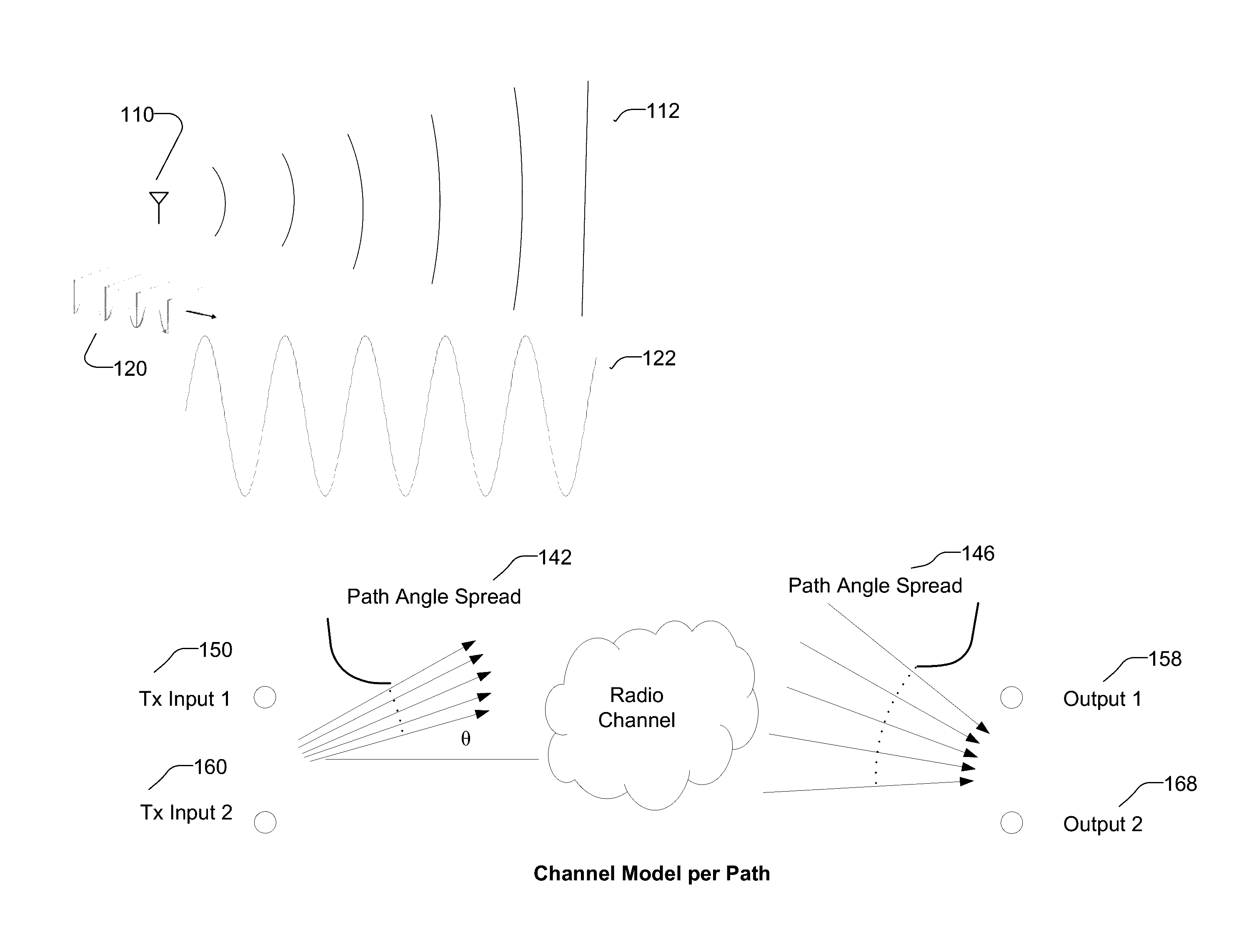
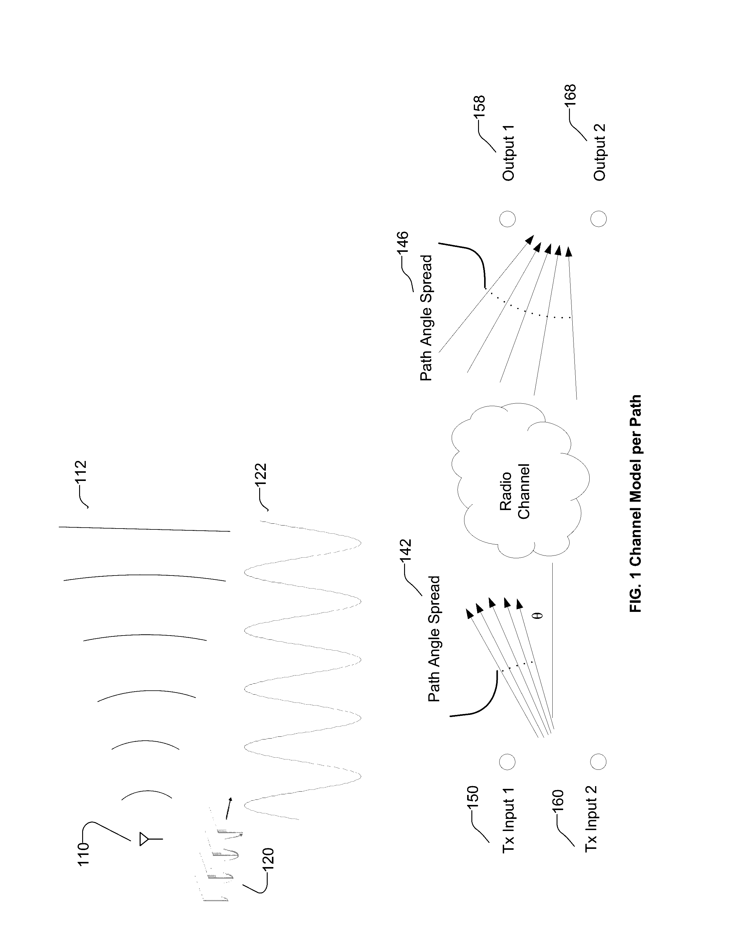
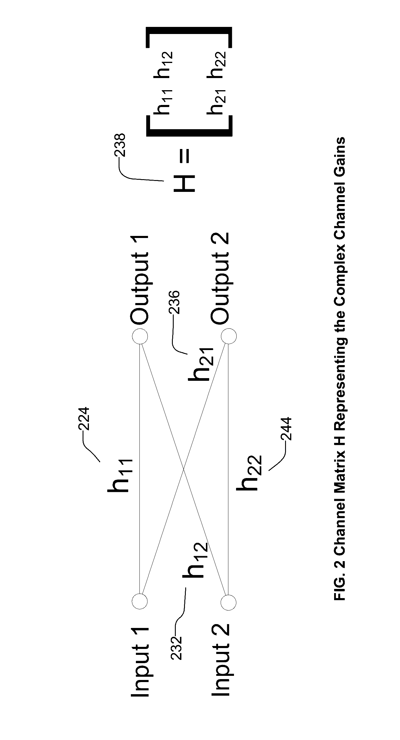
[0044]In the context of a relatively wide-bandwidth technology like LTE, it is important to emulate the spatial aspects of the wireless channel. FIG. 1 represents the channel model that is used to produce the complex path gains shown in FIG. 2. Transmit antenna 110 sends a signal modeled as a sinusoid 122; a group of transmit antennas send a...


PUM


Abstract

The disclosed technology relates to systems and methods for emulating a massive MIMO beamforming antenna array of arbitrary size—a channel model between a transmitter and a receiver, with one or more signal paths having respective amplitudes, angles of arrival, angle spreads, and delays. The disclosed technology includes defining a complete channel model H, calculating the correlation matrix for the channel, grouping the base antenna elements of the antenna array by combinations of signal and polarization, and calculating observed beamforming power of each group of the base elements, by applying a cross-correlation matrix to determine observed power signals and delay of each signal at each remote antenna element of the user equipment. Emulation includes supplying cross-correlated signals to remote antenna elements of user equipment during a RF test of the user equipment. Disclosed technology includes a channel emulator that generates output streams for testing user equipment for multiple users.

Description

RELATED APPLICATION[0001]This application is related to U.S. patent application Ser. No. 13 / 147,579, filed 29 Aug. 2011, entitled “Emulation and Controlled Testing of MIMO OTA Channels,” by John Douglass Reed, now U.S. Pat. No. 8,995,511, issued 31 Mar. 2015, which is incorporated by reference herein.BACKGROUND[0002]Massive multiple-input multiple-output (MIMO) provides an effective means for significantly increasing the capacity of cellular communication systems while possibly reducing their energy consumption. Multiple-Input-Multiple-Output (MIMO) antenna techniques are key factors in achieving the high data rates promised by next-generation wireless technologies such as LTE (Long-Term Evolution), LTE-Advanced and planned 5th generation technologies.[0003]MIMO systems are designed to take advantage of spatial diversity available in the propagation environment. The spatial diversity is quantified by the correlation between antennas, a function of both the propagation environment an...

Claims


Application Information

Patent Timeline
IPC IPC(8): H04B7/04
CPCH04B7/043H04B7/0413H04B17/391H04B17/3912
Inventor REED, JOHN DOUGLAS
Owner SPIRENT COMM
Why Eureka
Try Eureka