Method for estimation of probe shape in charged particle beam instruments

a technology of probe shape and beam instrument, which is applied in the direction of instruments, nuclear engineering, material analysis using wave/particle radiation, etc., can solve the problems of unclear contour of probe shape and incorrect shape finally obtained

Inactive Publication Date: 2010-10-21
HITACHI HIGH-TECH CORP
View PDF7 Cites 15 Cited by
  • Summary
  • Abstract
  • Description
  • Claims
  • Application Information

AI Technical Summary

Benefits of technology

[0018]In addition here, by adjusting focus deviation and image magnification, so that ratio between a pixel number composing a probe shape image in the just-focused state, and a pixel number composing a probe shape image in the de-focused state is roughly about 1:10 to 1:100 (a pixel number composing the probe shape image in the just-focused state of several pixels, and a pixel number composing the probe shape image in the de-focused state of from about several tens to hundred pixels), accuracy of the delta function approximation in the equation (5) (g0 represents the delta function, and G0* represents constant) is improved, and also correctness of the probe shape obtained is improved.
[0019]The present invention does not require filter processing operation because of not having a process of zero division in frequency space. Therefore, the present invention can provide the objective probe shape in more stably, as compared with the deconvolution method having instability of zero division. Furthermore, the present invention is suitable to automation.

Problems solved by technology

Furthermore, the deconvolution method had a problem that the probe shape finally obtained is incorrect, in such a way that in the case where an image data with low S / N ratio is used, contour of the probe shape becomes unclear or artifact may be commingled, by noises contained in the image data.

Method used


Image

  • Method for estimation of probe shape in charged particle beam instruments
  • Method for estimation of probe shape in charged particle beam instruments
  • Method for estimation of probe shape in charged particle beam instruments

Examples


embodiment 1

[0031]In the present embodiment, explanation will be given on an application example to a scanning electron microscope (SEM) that is capable of providing various functions such as length measurement, specimen inspection and the like. It should be noted that in the following explanation, “the just-focused state” means a state that the charged particle beam is converged onto a specimen surface, and “the de-focused state” means a state that the charged particle beam is not converged onto a specimen surface but is converged at the front or a far-side of the specimen surface at a light axis.

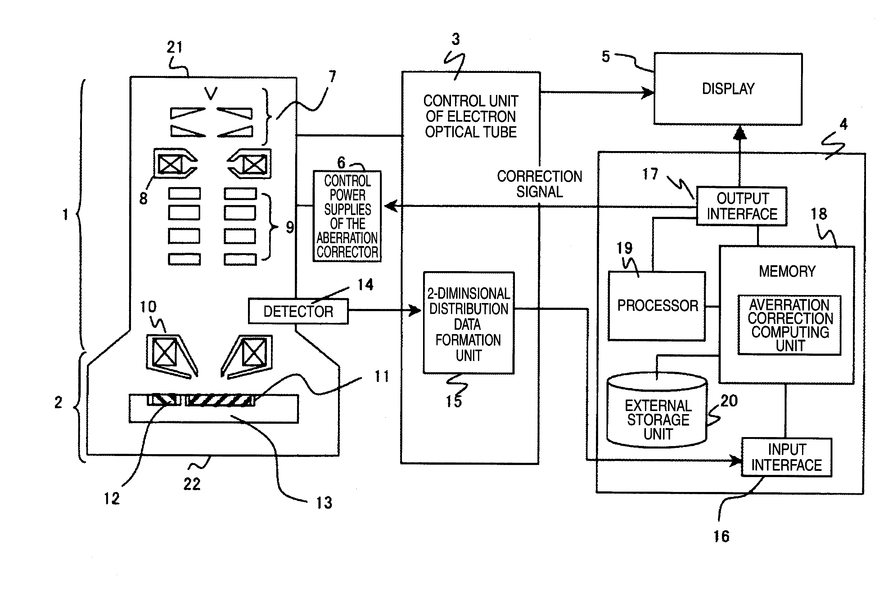
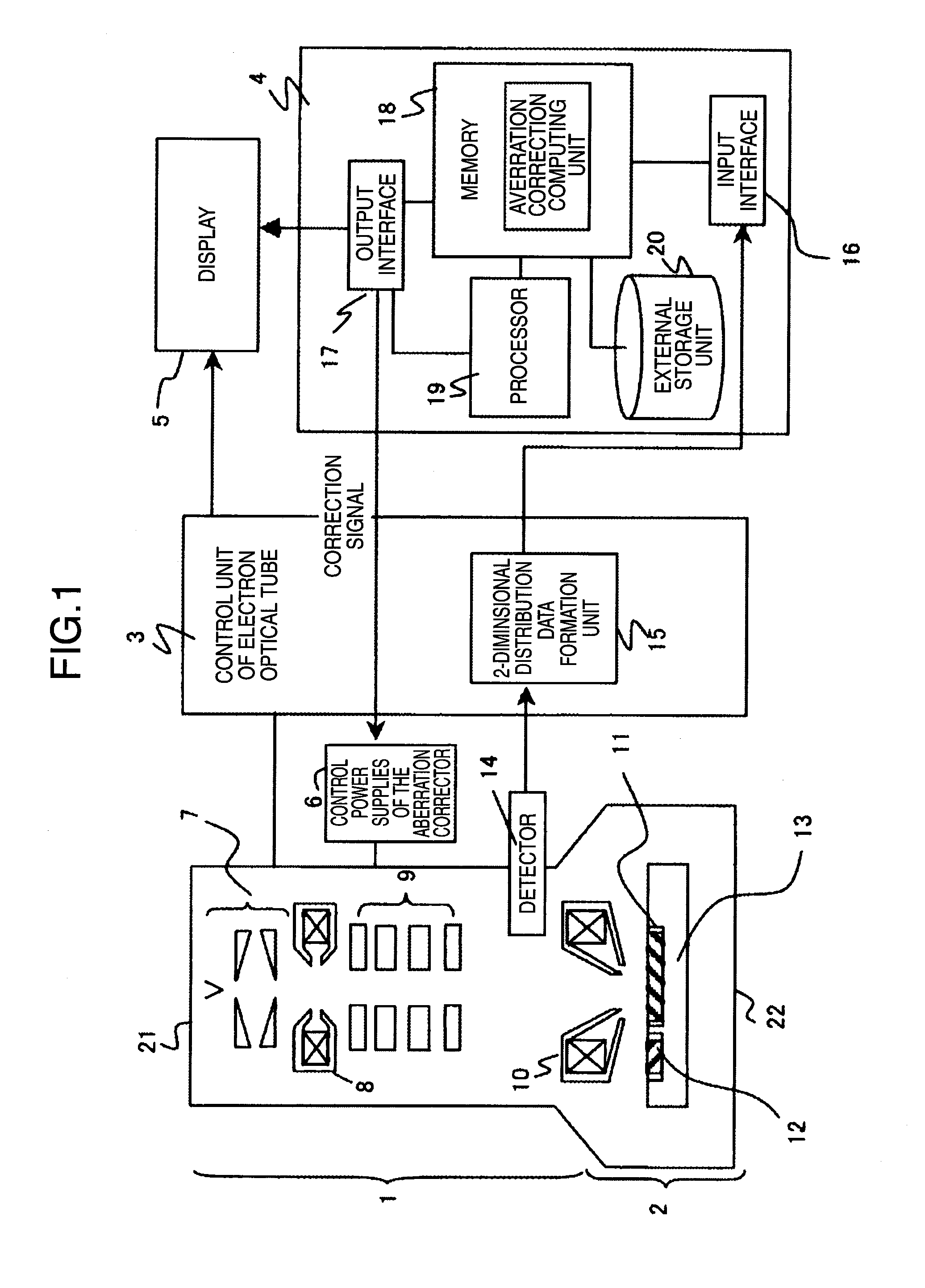
[0032]FIG. 1 shows a schematic drawing of the total constitution of SEM of the present embodiment. A system shown by FIG. 1 is consisted of, in rough classification, an electron optical tube 1 mounted with an aberration corrector, a specimen chamber 2 for storing the specimen, a control unit of electron optical tube 3 for controlling operation voltage or applied current for each of the elements of the...

embodiment 2

[0064]In the present embodiment, explanation will be given on an application example of the present invention to an optical microscope such as a confocal microscope or the like. In the case of an optical microscope or a confocal microscope, because aberration cannot be controlled by active control of an optical lens, a high resolution image can be obtained by determination of a point spread function at the just-focused state from a plurality of the de-focused amount, brightness distribution of the probe in the de-focused state, and optical constants (wavelength, NA value, refractive index of a medium and the like) of the microscope, and by execution of deconvolution of the just-focused image.

[0065]Explanation was given above on constitution examples of the present invention with reference to embodiment 1 and embodiment 2. Embodiment 1 relates to an example of an application instrument using an electron microscope, and Embodiment 2 relates to an example of an optical microscope, howe...


PUM


Abstract

A method for estimation of a probe shape, in a scanning electron microscope provided with an aberration corrector, and the method is designed so as to obtain a probe image, by inputting to a computer an image taken in a just-focused state and an image taken in a de-focused state, as an image data; preparing a correlation window by automatically determining a size of a correlation window image, based on an input data size and an output data size; executing cross-correlation calculation between the correlation window and a reference area; and repeating this calculation while shifting the reference area, so as to obtain a cross-correlation matrix, in order to stably obtain the probe image, without receiving effects of use conditions or noises.

Description

INCORPORATION BY REFERENCE[0001]The present application claims priority from Japanese application JP2006-343701 filed on Dec. 21, 2006, the content of which is hereby incorporated by reference into this application.BACKGROUND OF THE INVENTION[0002]The present invention relates to a method for automatic focusing, automatic astigmatic matching and automatic adjustment of an aberration corrector, or the like, of a scanning electron microscope, in particular, a scanning electron microscope (SEM) and a scanning transmission electron microscope (STEM).[0003]In an application instrument of a charged particle beam, such as an electron microscope or an ion beam processing instrument or the like, an observed image or a specimen is processed by irradiation of a convergent charged particle beam onto a specimen. Resolution or processing accuracy of these charged particle beam instruments is determined by a size of the convergent charged particle beam (probe), and in principle, smaller size of th...

Claims


Application Information

Patent Timeline
Patent Type & Authority Applications(United States)
IPC IPC(8): H01J37/28
CPCH01J37/21H01J2237/216H01J37/28H01J37/222
Inventor HIROSE, KOTOKOKAWASAKI, TAKESHIYODA, HARUONAKANO, TOMONORI
Owner HITACHI HIGH-TECH CORP
Why Eureka
Try Eureka