Foldable tent

a tent and folding technology, applied in tents/canopies, building types, constructions, etc., can solve the problems of increasing production difficulty, affecting reducing the quality of tents, so as to reduce production difficulty, reduce production costs, and reduce production costs

Active Publication Date: 2017-01-26
XIAMEN INNOVATION METAL PRODUCING
View PDF10 Cites 9 Cited by
  • Summary
  • Abstract
  • Description
  • Claims
  • Application Information

AI Technical Summary

Benefits of technology

[0005]In order to solve the technical problem described above and / or other problems, an objective of the present invention is to provide a foldable tent which modifies the limits that existing tents impose on the position of the connection sleeve, reduces production difficulty, requires fewer raw materials for its production, and reduces production costs.
[0017]In comparison to the prior art, the present invention has the following advantages:
[0018]1. The present invention modifies the limits that existing tents impose on the position of the connection sleeve, reduces production difficulty, requires fewer raw materials for its production, and reduces production costs.
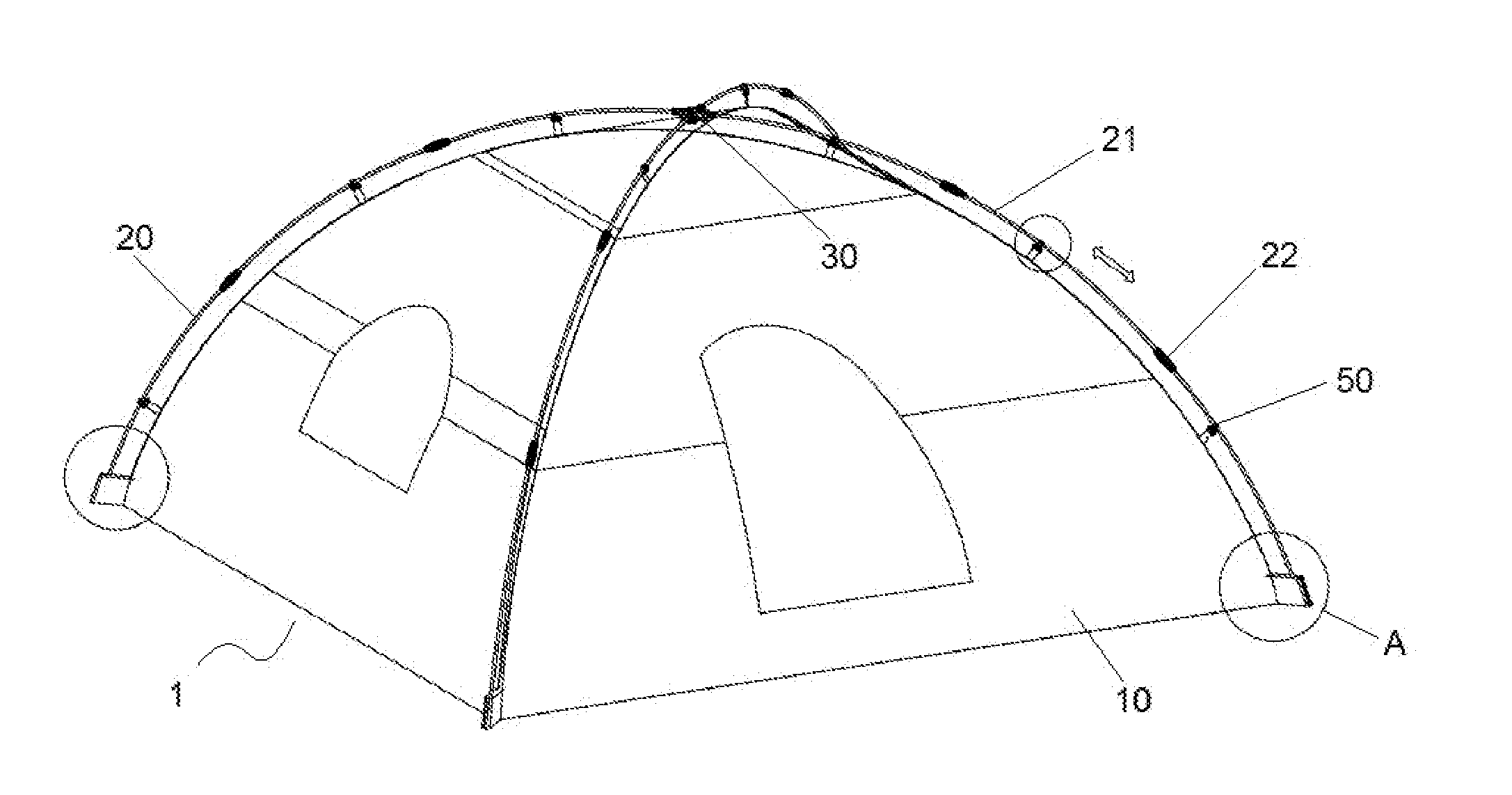
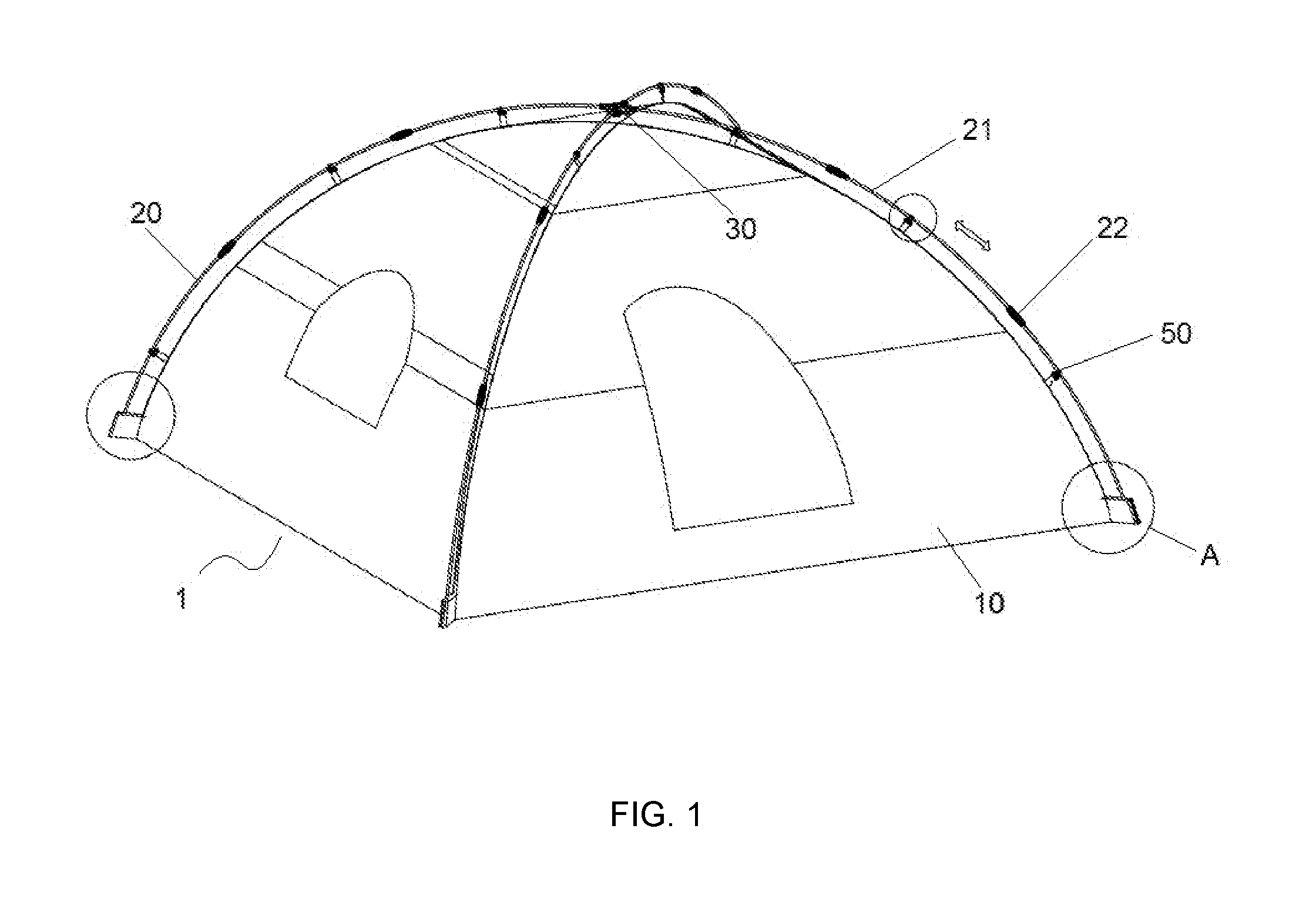
[0019]2. When disassembling the tent of the present invention, the support frame pole need not be separated from the tent cloth, such that the frame pole hook is always joined to the pole member and may slide on the pole member without becoming detached from the pole member; thus the subsequent unfolding of the tent is made easier: after the support frame poles are connected, assembly of the tent is complete. The tent of the present invention is simple and quick to assemble, and the time needed for assembling or disassembling the tent is greatly reduced.

Problems solved by technology

However, the connection sleeves must not be allowed to make unrestricted flipping motions; their positions must be limited.
However, the addition of the position-limiting plate not only increases the difficulty of production, but also necessitates the consumption of raw materials, which are needed in order to produce the position-limiting plate.
However, the aforementioned manner of pitching a tent is relatively complicated and requires a fairly long time to complete.

Method used


Image

  • Foldable tent
  • Foldable tent
  • Foldable tent

Examples


first embodiment

the Connection Member

[0046]The connection member is a U-shaped member 111, an opening of the U-shaped member is fixedly connected to the bottom of the tent cloth, and the other end of the support frame pole is disposed within the U-shaped member. Preferably, the U-shaped member is a cloth strap; the two ends of the cloth strap are stitched to the bottom of the tent cloth. When in use, one needs only place the other end of the support frame pole into the space enclosed by the cloth strap, as illustrated in FIG. 14.

second embodiment

the Connection Member

[0047]The connection member is a connection piece 112 made of plastic material, and a connection hole 113 is provided on the connection piece; a snap-connection member 60 is provided on one end of the support frame pole, and the snap-connection member is snap-connected in the connection hole. Specifically, the snap-connection member comprises a sleeve 61, one end of the sleeve is connected to a snap-connection block 62, and a notch 63 fitting the connection hole is provided on the snap-connection block. In addition, a pair of symmetrical notches is provided at the connection between the snap-connection block and the sleeve. The cross-section of the snap-connection-block end facing the notch is larger than the cross-section of the connection hole; the cross-section of one end of the sleeve also is larger than the cross-section of the connection hole. When in use, the snap-connection block is passed through the connection hole, causing the notch and the connection...


PUM


Abstract

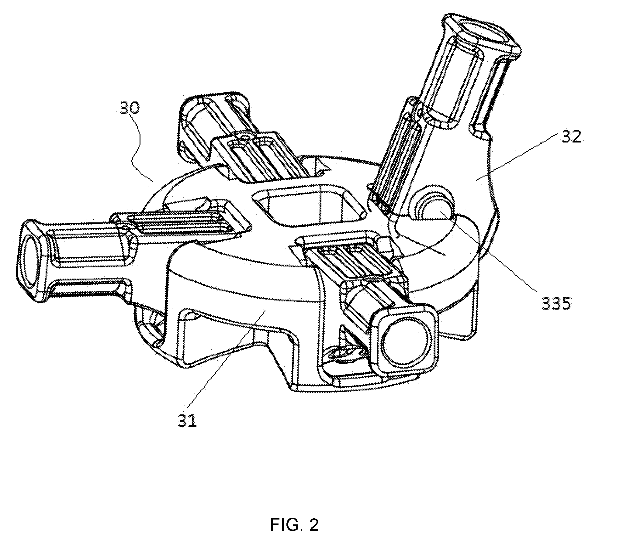
A foldable tent includes a tent cloth, a plurality of support frame poles to support the tent cloth, and a tent top supporting device. The tent top supporting device includes a cover, a plurality of connection sleeves, and a plurality of inwardly concave recesses. The plurality of inwardly concave recesses is disposed at a peripheral side of the cover. Each recess includes a first side wall and a second side wall disposed on two sides of the recess, and an inner side wall adjacent a center of the cover. Each respective connection sleeve is flippably or rotatably disposed in a corresponding recess, and has one end connected to an end of a corresponding support frame pole. When the foldable tent is unfolded, a side wall of the other end of the corresponding connection sleeve comes into contact and matches with the inner side wall of the corresponding recess.

Description

FIELD OF THE INVENTION[0001]The present invention relates to an outdoor product. More specifically, it relates to a foldable tent or a pole-type tent.BACKGROUND[0002]Along with continuing rises in living standards, more and more people have come to enjoy independent travel, and a considerable number of those people enjoy camping, outdoor adventures, cycling, and so on. Accordingly, tents, and especially small-size pole-type tents, have become essential items for travel.[0003]Yet common tent top supporting devices currently available on the market typically comprise a cover and a plurality of connection sleeves (the specific number of connection sleeves is dependent on the size of the tent); the connection sleeves are hingedly connected to the cover, which allows the connection sleeves to make a flipping motion along a certain axial line. However, the connection sleeves must not be allowed to make unrestricted flipping motions; their positions must be limited. Currently, a position-l...

Claims


Application Information

Patent Timeline
Patent Type & Authority Applications(United States)
IPC IPC(8): E04H15/42E04H15/32E04H15/36E04H15/54E04H15/64
CPCE04H15/425E04H15/54E04H15/322E04H15/36E04H15/64E04H15/48
Inventor JIN, JU YOUNG
Owner XIAMEN INNOVATION METAL PRODUCING
Why Eureka
Try Eureka