Radial permanent magnetic suspension bearing having micro-friction or no friction of pivot point

a technology of rotating point and bearing, which is applied in the direction of bearings, shafts and bearings, rotary machine parts, etc., can solve the problems of relative large support force and difficulty in adjusting suspension, and achieve the effect of reducing the amount of permanent magnets that would otherwise be used, facilitating production and assembly, and increasing suction force in the upward direction

Inactive Publication Date: 2017-01-26
LI GUOKUN +1
View PDF6 Cites 7 Cited by
  • Summary
  • Abstract
  • Description
  • Claims
  • Application Information

AI Technical Summary

Benefits of technology

[0019]According to the present invention, a stator pull-push magnet and a rotor pull-push magnet, which constitute an axial pull-push magnetic circuit, are disposed on a stator casing and a horizontal shaft, respectively. Particularly, the stator pull-push magnet is only disposed above the horizontal plane where the axle center of the horizontal shaft (that is, the upper half ring) is located. In this way, the amount of permanent magnet that would be otherwise used is greatly decreased, and the suction force in the upward direction is remarkably increased. In this way, the radial permanent magnetic suspension bearing is simply in the structure, facilitates production and assemble. Furthermore, its support force is relative large. Therefore, the load to the mechanical support bearing is greatly decreased, such that the support from the magnetic suspension bearing accounts more than otherwise. Furthermore, the radial gap may be adjusted, according to the load, so as to achieve micro-friction or no friction.

Problems solved by technology

CN 01136634.6 is complicated in structure, rendering it difficult to adjust suspension.
In the prior art, a partial permanent magnetic suspension (not complete permanent magnetic suspension) bearing is usually applied, however it is large in volume and heavy in weight for many mechanical transmission systems with rotation speed of 50,000 rpm or below, since the supporting force from the permanent magnetic suspension bearing is small and hence takes a small account of the supporting action to the shaft and load.
Furthermore, its support force is relative large.

Method used


Image

  • Radial permanent magnetic suspension bearing having micro-friction or no friction of pivot point
  • Radial permanent magnetic suspension bearing having micro-friction or no friction of pivot point
  • Radial permanent magnetic suspension bearing having micro-friction or no friction of pivot point

Examples


Embodiment Construction

[0033]Hereinafter the invention will be further explained with reference to the accompanying figures.

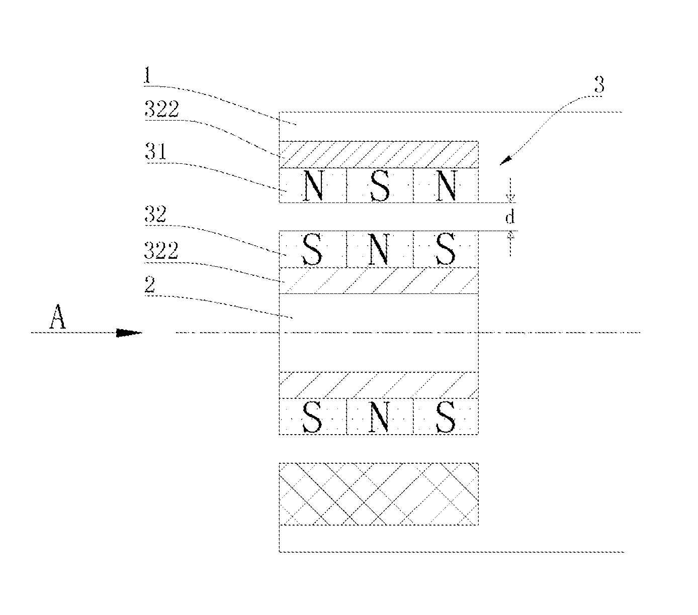
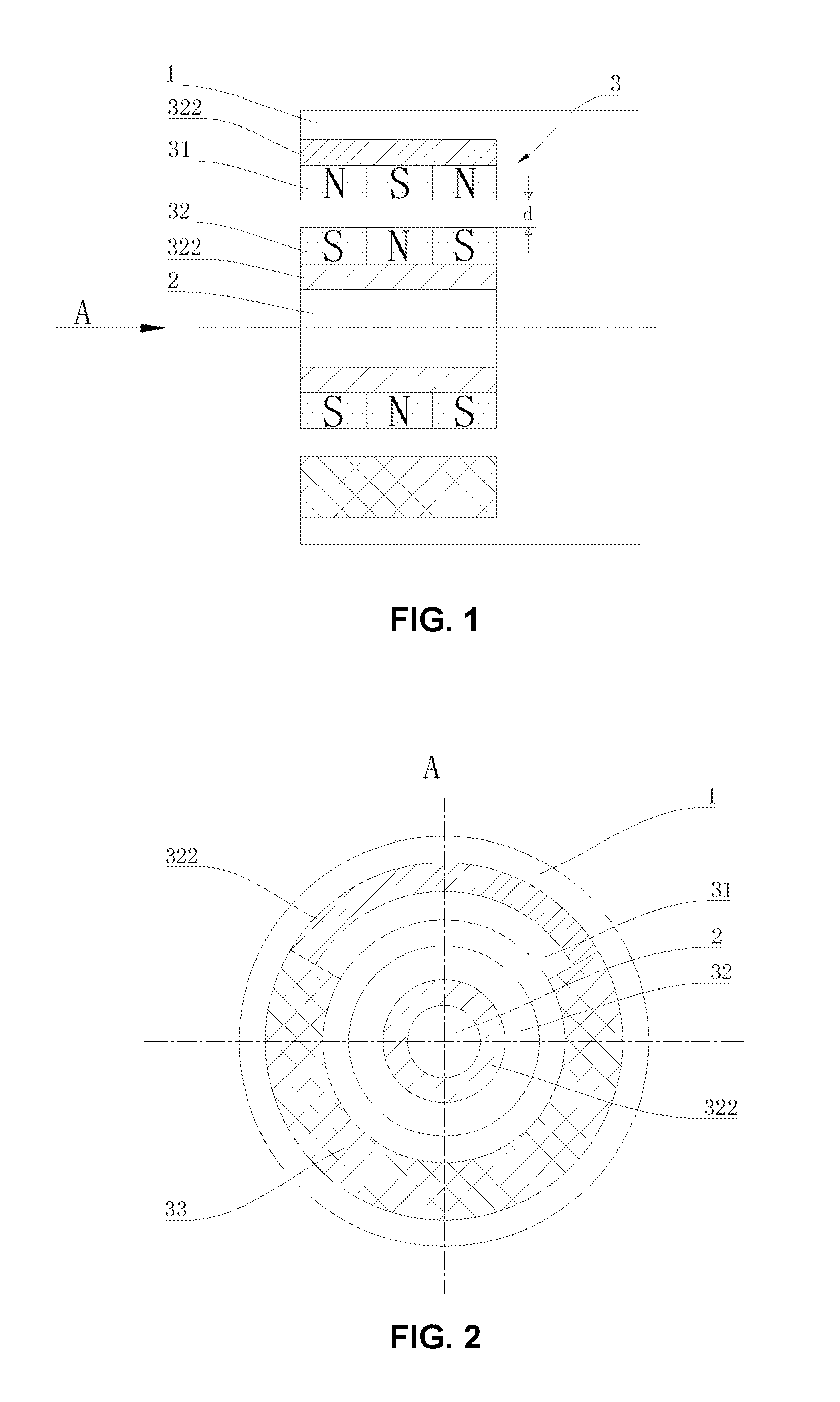
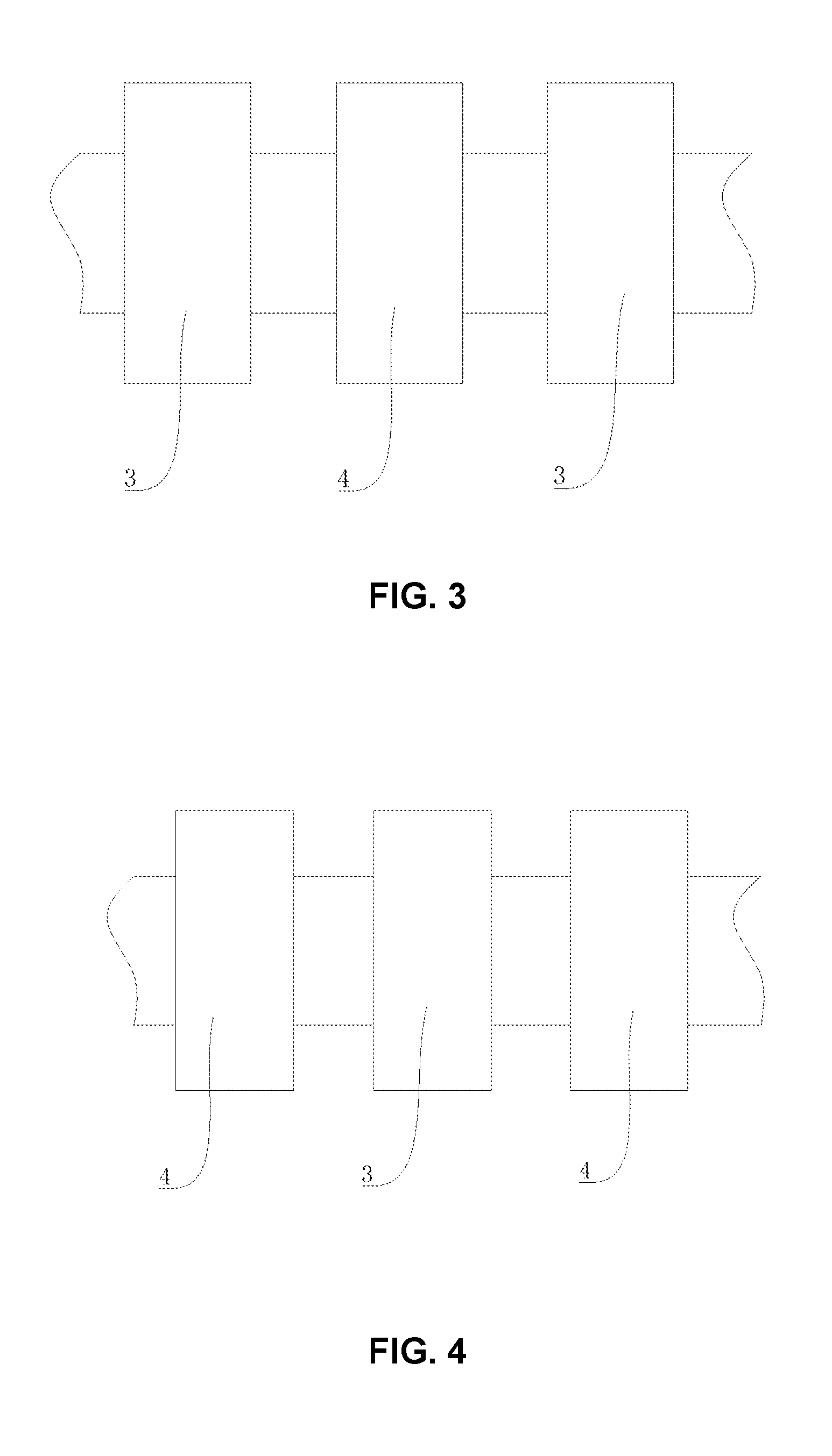
[0034]Referring to FIG. 3 and FIG. 4, a radial permanent magnetic suspension bearing having micro-friction or no friction of pivot point according to the present invention comprises a support bearing 4 as pivot point disposed on a horizontal shaft 2, and a permanent magnetic suspension bearing 3 disposed on the horizontal shaft 2 and spaced from the support bearing 4 by an axial distance. Returning to FIG. 1, the permanent magnetic suspension bearing 3 comprises a stator pull-push magnet 31 disposed on a stator casing 1 through a permeability magnetic substrate 322, and a rotor pull-push magnet 32 disposed on the horizontal shaft 2 correspondingly via an annular permeability magnetic substrate 322, having a radial gap d and forming an axial pull-push magnetic circuit with the stator pull-push magnet 31. The rotor pull-push magnet 32 consists of two or more annual permanent magnets ax...


PUM


Abstract

A radial permanent magnetic suspension bearing, comprising: a horizontal shaft (2), a support bearing (4), and a radial permanent magnet suspension bearing (3); the permanent magnetic suspension bearing (3) comprises a stator pull-push magnet (31) disposed on a stator casing (1) via a permeability magnetic substrate (322), and a rotor pull-push magnet (32) disposed on the horizontal shaft (2) correspondingly via an annular permeability magnetic substrate (322), having a radial gap and forming an axial pull-push magnetic circuit with the stator pull-push magnet (31); wherein the rotor pull-push magnet (32) consists of two or more annual permanent magnets axially and closely fitting, with magnetic poles alternately arranged in the axial direction; the stator pull-push magnet (31) consists of two or more annular permanent magnets axially and closely fitting, with magnetic poles alternately arranged in the axial direction, disposed over the horizontal panel where the axle center of the horizontal shaft (2) is located, and being symmetrical about the perpendicular bisection plane of the horizontal shaft. The bearing has a simple structure and greatly reduces energy consumption, without wear or bearing maintenance.

Description

TECHNICAL FIELD OF THE INVENTION[0001]The present invention relates to a bearing, particularly, to a radial permanent magnetic suspension bearing with pivot point.BACKGROUND ART[0002]The invention CN 01136634.6, titled as magnetic suspension bearing, and submitted by the first inventor of the present application in 2001, relates to a solution in which permanent magnets are used to constitute a pull-push magnetic circuit so as to form a magnetic suspension bearing without pivot point. The invention CN 200710099004.X submitted in 2007, titled as Repel push magnetic body component, complete permanent magnetism complete suspending bearing as well as combined wind power photovoltaic power generation system, discloses a solution in which permanent magnets are used to constitute a pull-push magnetic circuit so as to form a magnetic suspension bearing without pivot point.[0003]However, as to a radial bearing, the pull-push magnetic circuit used for the complete permanent magnetism and compl...

Claims


Application Information

Patent Timeline
Patent Type & Authority Applications(United States)
IPC IPC(8): F16C32/04F16C39/06
CPCF16C32/0412F16C2240/26F16C39/063
Inventor LI, GUOKUNWANG, CHAOXIAN
Owner LI GUOKUN
Why Eureka
Try Eureka