
Method and apparatus for sensing inter-modulation to improve radio performance in single and dual tuner

a technology of intermodulation and sensing apparatus, applied in the field of vehicles, can solve problems such as intermodulation distortion arising, front end overload distortion, clipping distortion at the intermediate frequency analog-to-digital conversion chain process,

Inactive Publication Date: 2017-01-26
PANASONIC AUTOMOTIVE SYST OF AMERICA
View PDF1 Cites 7 Cited by
  • Summary
  • Abstract
  • Description
  • Claims
  • Application Information

AI Technical Summary

Benefits of technology

The invention prevents the radio from tuning to a specific intermodulation artifact during certain operations, which improves the quality of the signal.

Problems solved by technology

A first type of distortion is front end overload distortion where transmission from a nearby station overwhelms the car radio's RF digital signal processing (DSP) receiver.
Front end overload can lead to clipping distortion at the intermediate frequency analog-to-digital conversion chain process.
However, since the overload affects the entire FM frequency range, the radio frequency (RF) designer is presented with the challenge of accommodating both strong and weak signal reception in such a scenario.
A second type of distortion is inter-modulation distortion arising from the use of non-linear devices.
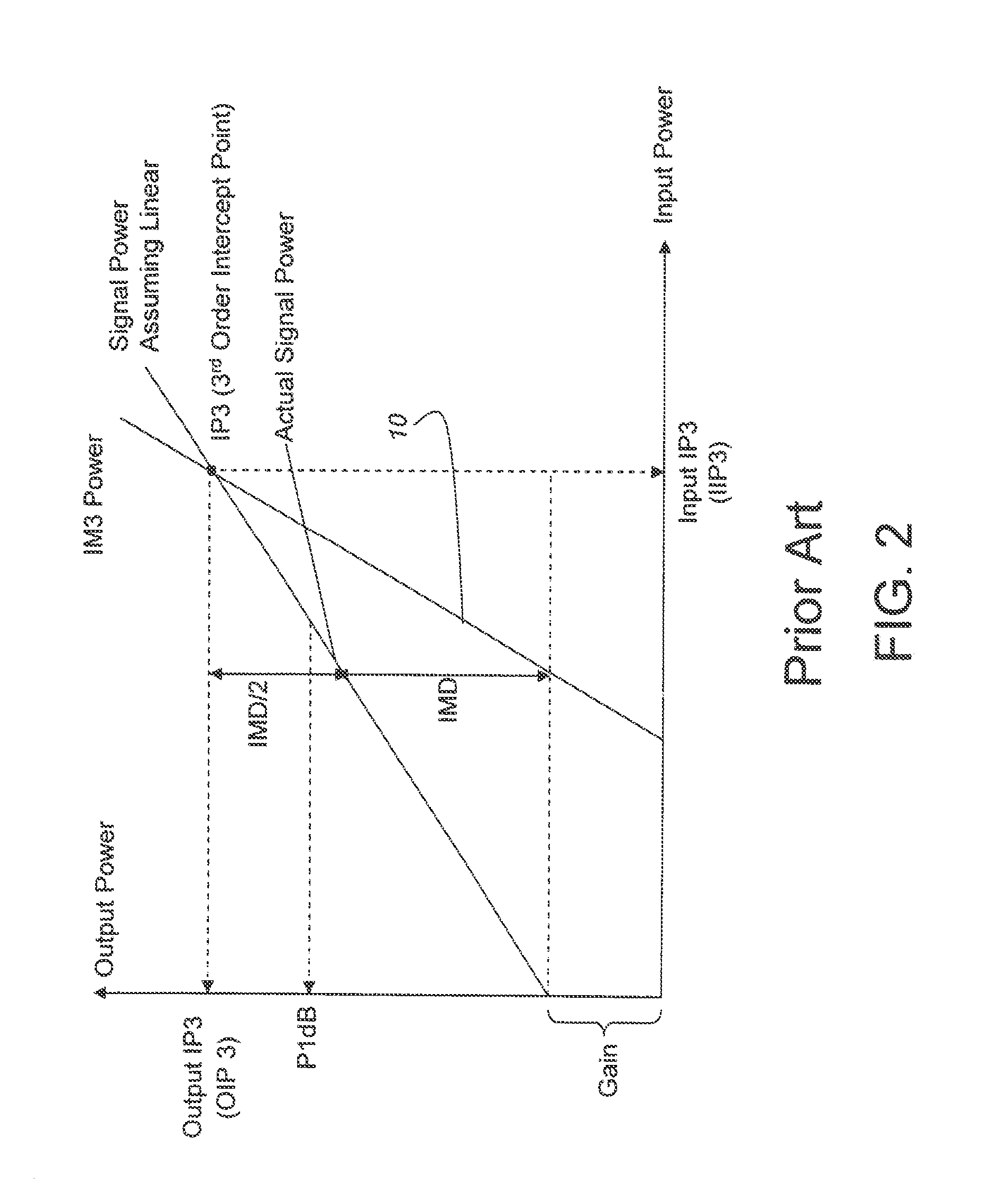
Inter-modulation occurs when the input to a non-linear device (NLD) is composed of two or more frequencies of high signal levels and results in the creation of frequency artifacts that are a product of the inputs.
These artifacts can result in either new ‘phantom’ stations (e.g., artifacts occur on frequencies where no valid station exists in the vicinity of the car radio) or overlap on a existing valid frequency.
Signals of a level exceeding 70 dBuV are considered strong signals and when mixed with other strong signals in the vicinity of the car, can lead to third order inter-modulation artifacts.
While inter-modulation distortion in the car radio can be of second order and third order types, the third order inter-modulation poses a bigger problem than second order inter-modulation.
However, third order inter-modulation is harder to filter out as it lies very close to the center frequency of the frequency tuned by the radio head unit.
A filter with characteristics steep enough to filter out third order inter-modulation but leave the tuned frequency intact is difficult to achieve.
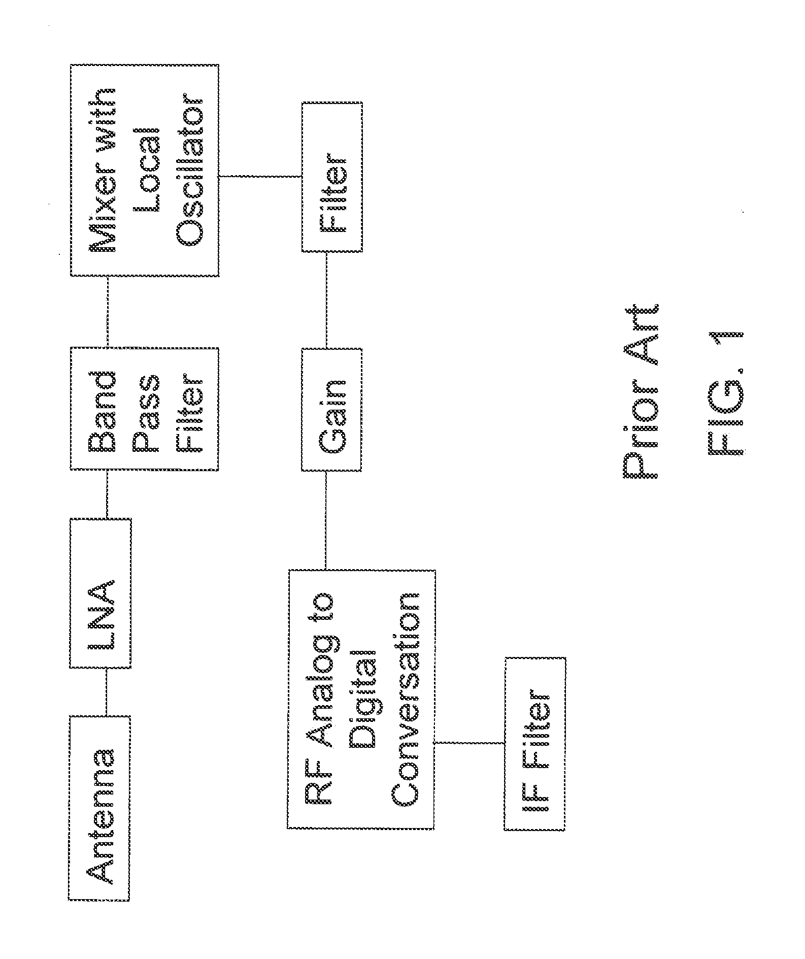
Illustrated FIG. 1 is an example of typical prior art RF receiver topology that results in the creation of inter-modulation artifacts.
For Global A boards, for example, the third order inter-modulation is between 10 and 15 dBuV and is known to cause audio distortion.
Because of the difficulty in filtering the third order inter-modulations, this poses a serious reception problem.

Method used


Image

  • Method and apparatus for sensing inter-modulation to improve radio performance in single and dual tuner
  • Method and apparatus for sensing inter-modulation to improve radio performance in single and dual tuner
  • Method and apparatus for sensing inter-modulation to improve radio performance in single and dual tuner

Examples


Embodiment Construction

[0054]The embodiments hereinafter disclosed are not intended to be exhaustive or limit the invention to the precise forms disclosed in the following description. Rather the embodiments are chosen and described so that others skilled in the art may utilize its teachings.

[0055]In one embodiment, the method enables the radio to build up signal level metrics of frequencies in the FM band in a memory repository and then utilize the information using the formulae such as (1) and (2) below in identifying the artifact:

L*f1+ / −M*f2+ / −N*f3, where f1, f2 and f3 are distinct frequencies and L+M+N=3, where L, M and N are integers   (1)

OR from

L*f1+ / −M*f2, where f1, f2 are distinct frequencies and L+M=3, where L and M are integers   (2)

The way the information is updated in the repository memory area may vary between single and dual tuner.

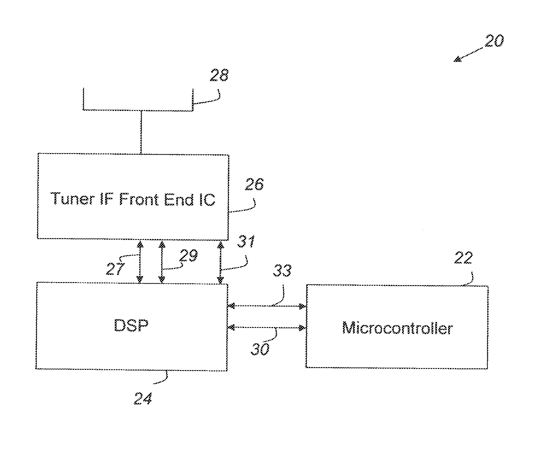
[0056]Referring now to FIG. 8, there is shown one embodiment of a single tuner radio system 20 of the present invention. Radio system 20 may include a microcontrol...


PUM


Abstract

A method of performing alternate frequency switching in a radio includes tuning the radio to a primary frequency. A candidate alternate frequency is identified. It is determined whether the candidate alternate frequency is a third order inter-modulation artifact. Tuning is switched from the primary frequency to the candidate alternate frequency only if it is determined in the determining step that the candidate alternate frequency is not a third order inter-modulation artifact.

Description

CROSS-REFERENCE TO RELATED APPLICATION[0001]This application is a continuation of U.S. patent application Ser. No. 14 / 507,983, filed on Oct. 7, 2014 which is currently under allowance, which is a continuation of U.S. patent application Ser. No. 13 / 892,792, filed on May 13, 2013, now U.S. Pat. No. 8,886,142, issued on Nov. 11, 2014, which is continuation of U.S. patent application Ser. No. 13 / 010,225, filed on Jan. 20, 2011, now U.S. Pat. No. 8,463,216, issued on Jun. 11, 2013, the disclosures of which are hereby incorporated by reference in their entireties for all purposes.BACKGROUND OF THE INVENTION[0002]1. Field of the Invention[0003]The present invention relates to radios for use in vehicles, and, more particularly, to improving signal reception quality in radios for use in vehicles.[0004]2. Description of the Related Art[0005]Car radio reception quality is an important element of overall consumer vehicle satisfaction. Consequently, car original equipment manufacturers (OEMs) an...

Claims


Application Information

Patent Timeline
Patent Type & Authority Applications(United States)
IPC IPC(8): H04B1/10H04B17/345
CPCH04B1/1027H04B2001/1072H04B17/345H03J1/0008H04B1/082H04H20/26H04H2201/60H04H2201/13H04W52/0209H04B1/1036Y02D30/70H04L25/08
Inventor THOMAS, DONALDHINGERTON, JASONFUJISAWA, TATSUYACHU, JAMMIEJAISIMHA, SHREEBAILLARGEON, ROBERT
Owner PANASONIC AUTOMOTIVE SYST OF AMERICA
Learn More