
Smart home wireless control system

a wireless control system and smart home technology, applied in the field of smart home wireless control system, can solve the problems of tedious operation process, inapplicability, and inability to meet the needs of users, and achieve the effect of high intelligence level

Active Publication Date: 2017-01-26
GUANGDONG CLOUD CORNER INTELLIGENT TECH CO LTD
View PDF3 Cites 30 Cited by
  • Summary
  • Abstract
  • Description
  • Claims
  • Application Information

AI Technical Summary

Benefits of technology

The present invention is a smart home remote control system that can automatically complete the entire operation process and has high intelligence level. The same mobile phone can be used for various multifunctional appliances with different demands. The control interface is quickly presented to the user, so the user does not need excessive operations and does not need to configure and use multiple remote controllers. This results in a more efficient and user-friendly environment. Additionally, the user does not need to worry about electricity waste caused by forgotten devices. Overall, the entire home appliances become smarter and more environmentally friendly.

Problems solved by technology

However, the present smart systems continuously use a conservative design idea, and are lack of innovation, resulting in that people feel most smart systems are not smart in practical application and experience.
Not only the functions are not practical, but the operating process is tedious.
It seems extremely tedious to switch layer-by-layer menus and interfaces on a control interface, finally find a related device and then operate; instead, the combined control of directly operating or installing such a device as an acousto-optic sensing device in front of a switch of the device seems to be more practical and effective; meanwhile, special training caused by the overturning of habits for using the smart system also makes users, particularly the old and children at home, to gradually lose interest on the smart home, which greatly reduces the practical value of the smart home.

Method used


Image

  • Smart home wireless control system
  • Smart home wireless control system
  • Smart home wireless control system

Examples


Embodiment Construction

[0026]In order to represent the technical solution of the present invention more clearly, the present invention will be further explained with reference to the drawings hereinafter.

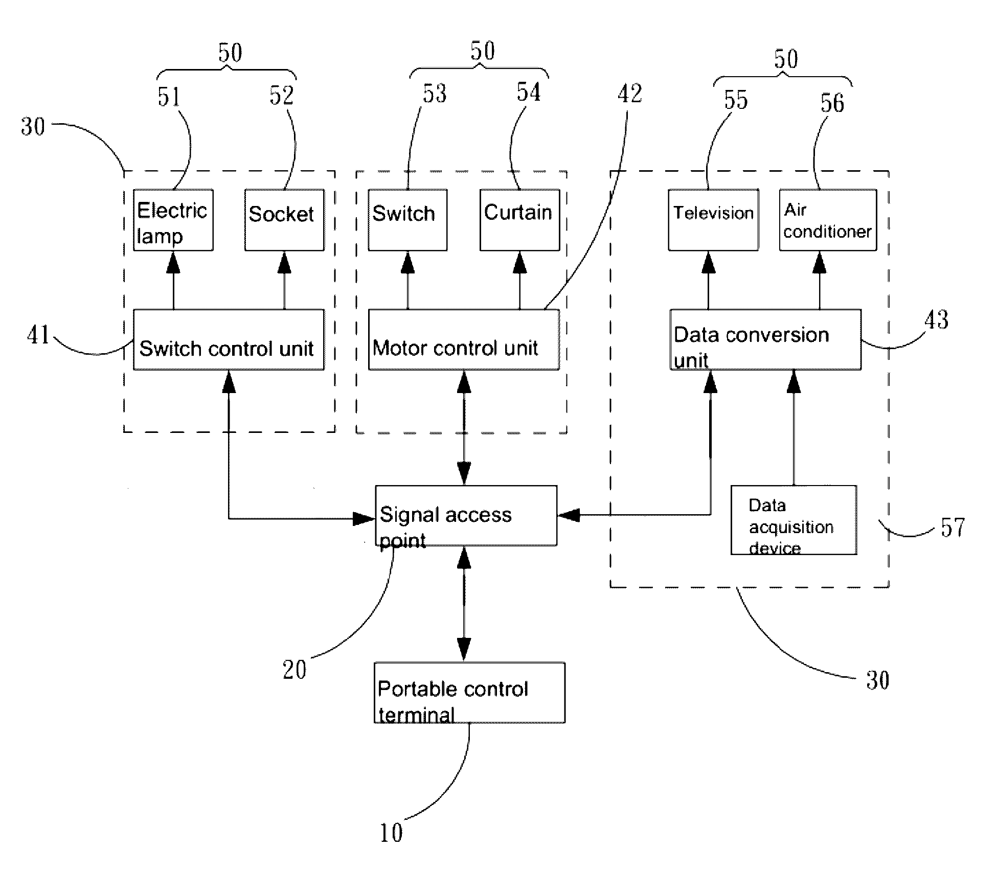
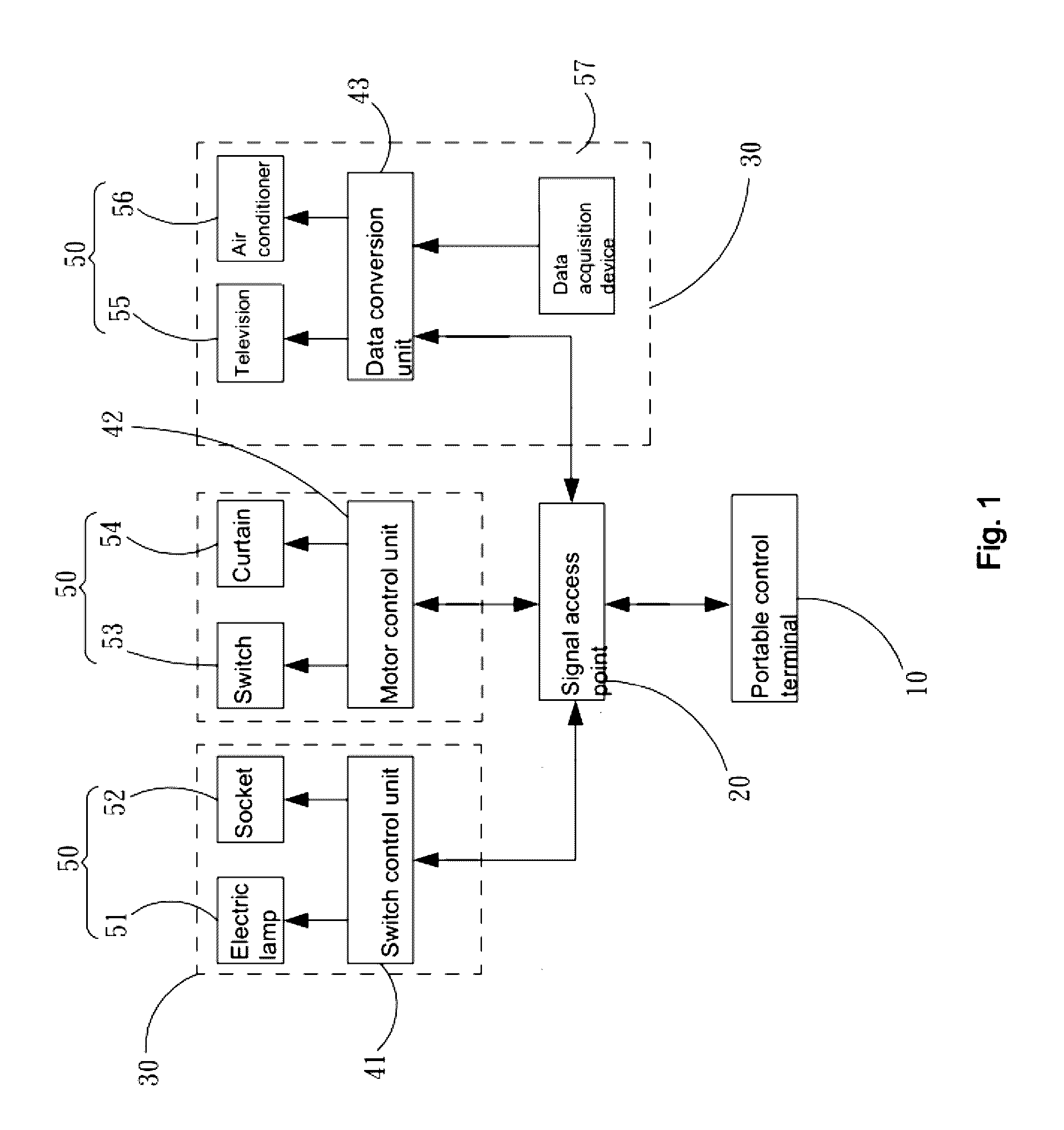
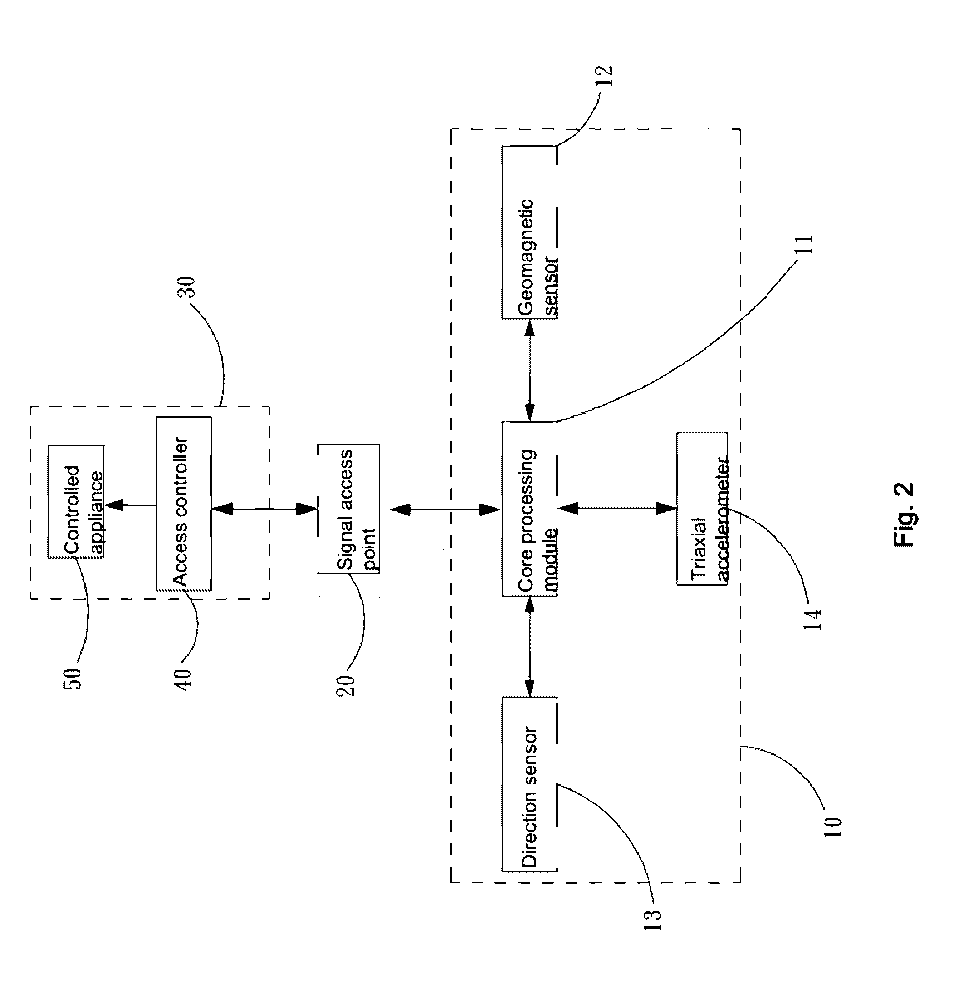
[0027]Referring to FIG. 1 to FIG. 4, the present invention provides a smart home remote control system. The smart home remote control system includes a mobile control terminal 10, a plurality of remote-controlled devices 30 and a signal access point 20 (hereinafter referred to as AP), wherein the remote-controlled devices 30 are installed on different positions indoors such as room, hall or the like; the AP produces a WIFI signal, both the mobile control terminal 10 and the remote-controlled devices 30 are connected to the AP through the WIFI signal. The mobile control terminal 10 and the remote-controlled devices 30 exchange data through the AP, the mobile control terminal can control the remote-controlled devices 30, for example, light on-off, temperature regulation, television program selection and the...


PUM


Abstract

A smart home wireless control system includes a mobile control terminal, a plurality of remote-controlled devices and a signal access point (AP), wherein the mobile control terminal and the remote-controlled devices exchange data through the AP, each remote-controlled device includes an access controller and a controlled appliance connected to the access controller, the inside of the access controller is provided with a wireless signal station and a counter, the mobile control terminal detects the signal intensities of the wireless signal stations of each remote-controlled device, and the mobile control terminal conducts smart control on the remote-controlled devices according to the changes of the received signal intensities of the remote-controlled devices.

Description

FIELD OF THE INVENTION[0001]The present invention relates to the field of home control systems, and more particularly, to a smart home wireless control system.BACKGROUND OF THE INVENTION[0002]With the development of technology and increasing life standards of the public, functions of such technology products as smartphone, tablet, smart devices and the like are getting perfect, the performances thereof are getting powerful, and the popularization degrees thereof are getting higher. More people join in the ranks of pursuing efficiency and experiencing higher life standards, and are full of expectation on conveniences that may be possibly brought by a smart system.[0003]However, the present smart systems continuously use a conservative design idea, and are lack of innovation, resulting in that people feel most smart systems are not smart in practical application and experience. Not only the functions are not practical, but the operating process is tedious. It seems extremely tedious t...

Claims


Application Information

Patent Timeline
Patent Type & Authority Applications(United States)
IPC IPC(8): H04L12/28G08C17/02G08C23/04H04W4/02H04W4/021
CPCH04L12/2821H04L12/2827H04W4/021H04L2012/2841G08C23/04H04L2012/285G08C17/02H04L12/282G06F3/0346
Inventor PAN, FEIJIAN
Owner GUANGDONG CLOUD CORNER INTELLIGENT TECH CO LTD
Learn More