Dynamic peak power limiting to processing nodes in an information handling system

a technology of information processing system and peak power, applied in the field of information handling system, can solve problems such as reducing the amount of incoming ac power, and achieve the effect of limiting peak power consumption in processing nodes

Active Publication Date: 2017-02-02
DELL PROD LP
View PDF5 Cites 33 Cited by
  • Summary
  • Abstract
  • Description
  • Claims
  • Application Information

AI Technical Summary

Benefits of technology

[0007]Disclosed are a computer-implemented method and an information handling system (IHS) to dynamically limit peak power consumption in processing nodes of an IHS. According to one embodiment, the method comprises receiving, at a power management micro-controller, processing node-level power-usage and workload data from several node controllers, including current power consumption and a current workload, for each processing node within the IHS. A total available system power of the IHS is identified including a peak power output capacity and a sustained output power capacity. At least one node peak power threshold is determined based on the power-usage and workload data for each of the processing nodes. The node controllers are triggered to determine and set a device peak power limit for each of several variable performance devices within each of the processing nodes based on the node peak power threshold, where each of the variable performance devices dynamically adjusts a corresponding device performance metric, such as a corresponding one of an operating frequency and data throughput, based on the device peak power limit.

Problems solved by technology

During operation of an information handling system, events can occur that interrupt or reduce the amount of incoming AC power to the information handling system or the amount of available power from power supplies that deliver electrical power to the information handling system.

Method used


Image

  • Dynamic peak power limiting to processing nodes in an information handling system
  • Dynamic peak power limiting to processing nodes in an information handling system
  • Dynamic peak power limiting to processing nodes in an information handling system

Examples


Embodiment Construction

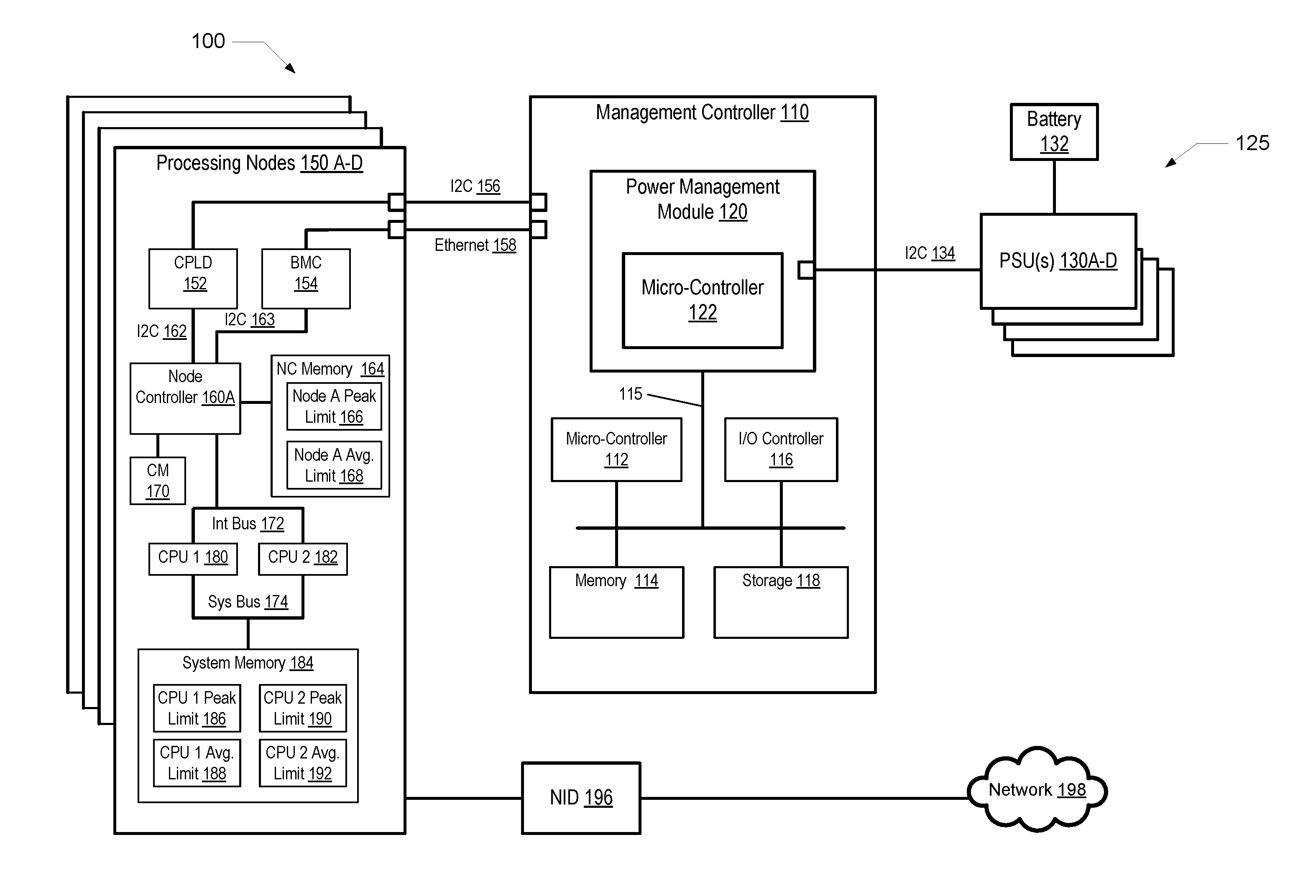
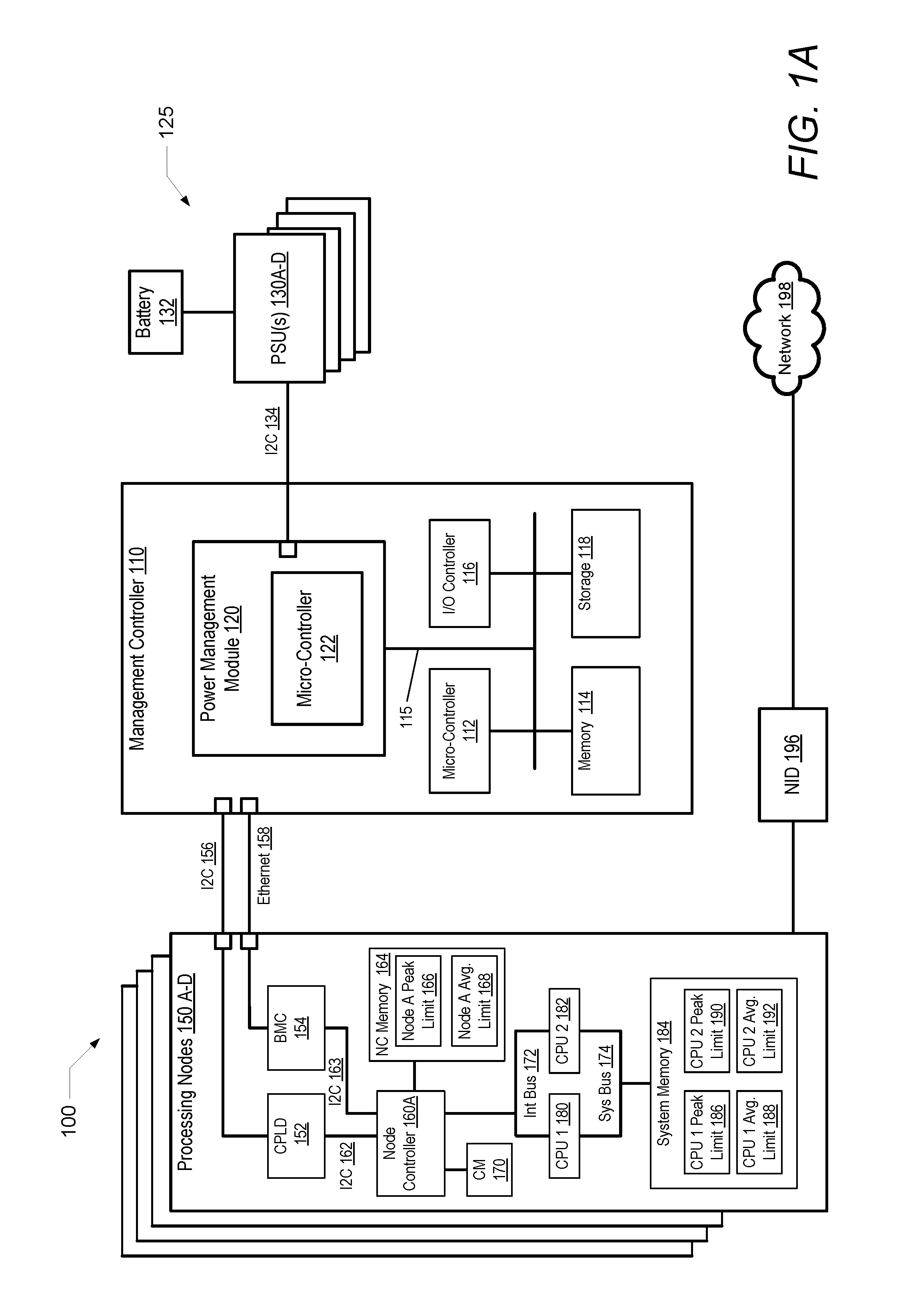
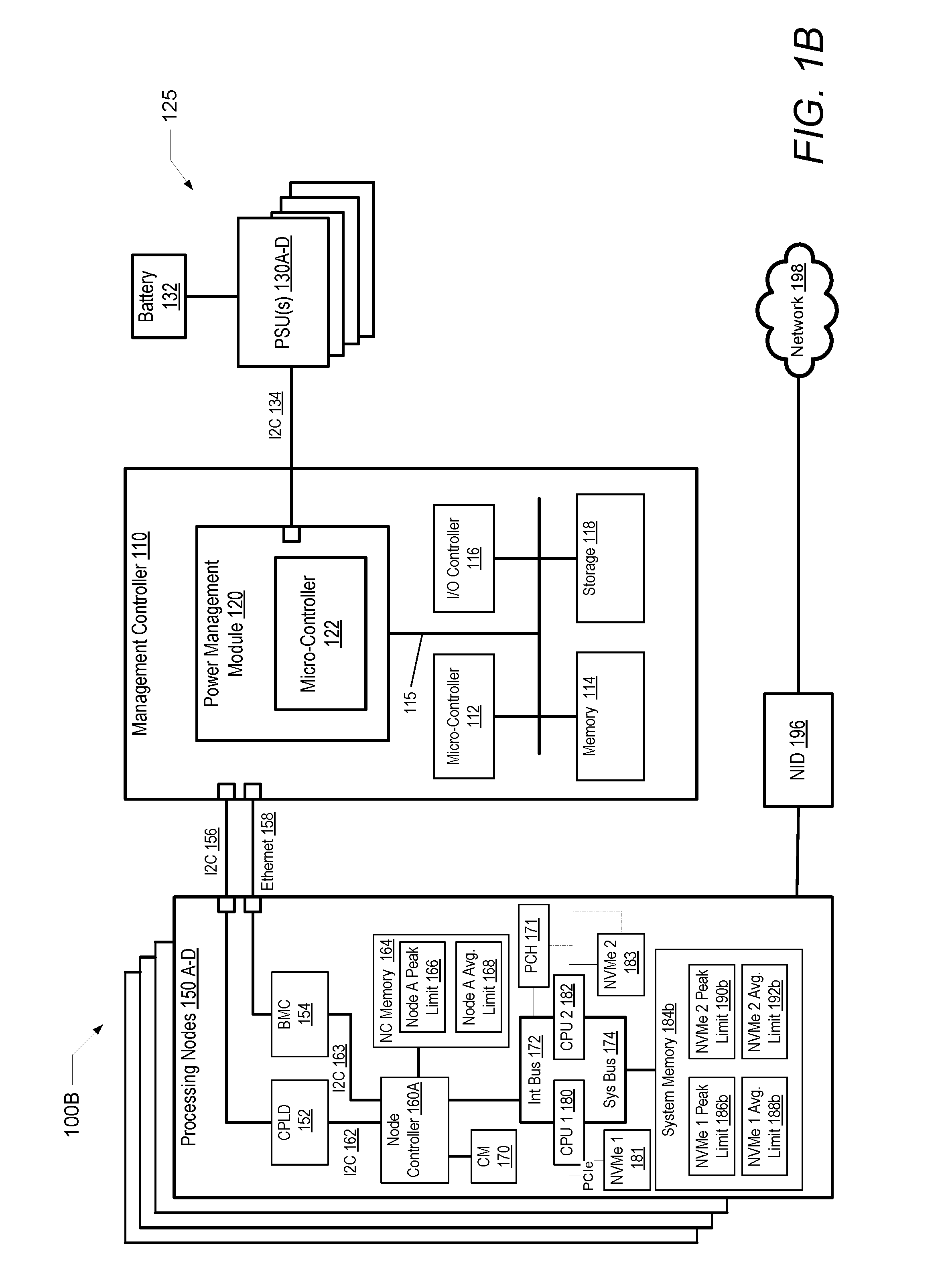
[0032]The illustrative embodiments provide an information handling system (IHS) and a method performed within the IHS that dynamically limits peak power consumption in processing nodes of the IHS. According to one embodiment, the method comprises receiving, at a power management micro-controller, processing node-level power-usage and workload data from several node controllers, including current power consumption and a current workload, for each processing node within the IHS. A total available system power of the IHS is identified including a peak power output capacity and a sustained output power capacity. At least one node peak power threshold is determined based on the power-usage and workload data for each of the processing nodes. The node controllers are triggered to determine and set a device peak power limit for each of several variable performance devices within each of the processing nodes based on the node peak power threshold, where each of the variable performance level...


PUM


Abstract

A computer-implemented method dynamically limits peak power consumption in processing nodes of an IHS. A power management micro-controller receives processing node-level power-usage and workload data from several node controllers, including current power consumption and a current workload, for each processing node within the IHS. A total available system power of the IHS is identified including a peak power output capacity and a sustained output power capacity. At least one node peak power threshold is determined based on the power-usage and workload data for each of the processing nodes. The node controllers are triggered to determine and set a device peak power limit for each of several variable performance devices within each of the processing nodes based on the node peak power threshold, wherein each of the variable performance devices dynamically adjusts a value of a corresponding device performance metric based on the device peak power limit.

Description

PRIORITY[0001]The present application is a continuation-in-part (OP) of and claims priority benefit from U.S. patent application Ser. No. 14 / 816,031, filed Aug. 2, 2015, titled “Dynamic Peak Power Limiting To Processing Nodes In An Information Handling System,” which is a OP of and claims the benefit of priority from U.S. application Ser. No. 13 / 598,966, filed Aug. 30, 2012, titled “Information Handling System Configuration for Power System Output Capability,” which has now issued as U.S. Pat. No. 9,098,277. The entire content of both priority Applications is hereby incorporated herein by reference.BACKGROUND[0002]1. Technical Field[0003]The present disclosure generally relates to information handling systems and in particular to dynamic peak power limiting to processing nodes in an information handling system.[0004]2. Description of the Related Art[0005]As the value and use of information continue to increase, individuals and businesses seek additional ways to process and store inf...

Claims


Application Information

Patent Timeline
Patent Type & Authority Applications(United States)
IPC IPC(8): G06F1/32G06F1/28G06F1/26
CPCG06F1/3296G06F1/266G06F1/3275G06F1/3225G06F1/28G06F1/3206G06F1/3234G06F1/324G06F1/3246
Inventor KHATRI, MUKUND P.KURUVILA, BINAY A.JENNE, JOHN ERVEN
Owner DELL PROD LP
Why Eureka
Try Eureka