Alternator system

a technology of alternators and belts, applied in the direction of electric generator control, process and machine control, instruments, etc., can solve the problems of system inability to provide the high power required, and the function of vehicle windshields requires a significant amount of power

Inactive Publication Date: 2003-02-27
ECOAIR
View PDF0 Cites 50 Cited by
  • Summary
  • Abstract
  • Description
  • Claims
  • Application Information

AI Technical Summary

Problems solved by technology

Even if the system is de-tuned from the optimum power at idle and is designed only to provide the required power at idle and the required power at high speed, this approach would lead to a much larger alternator exhibiting excess inertia, belt slip and difficulty of high speed operation.
Such a system is not practical for providing the high power required by electronic valve actuation systems.
Typically, an electronic de-icing function for vehicle windshields requires a significant amount of power to effect rapid ice removal before the vehicle is driven.
Furthermore, the de-icing system may require a relatively larger operating voltage, e.g. 42 volts to meet constraints associated with the windshield technology.
Issues of size, inertia, high low speed torque, belt slip and required high-speed operation combine to make this a very difficult alternator design issue.
However a Lundell system designed to maximize power at idle would only provide a 40-50% increase in power at these elevated speeds which is still not sufficient to avoid a substantial increase in the size of the alternator.
There are also power benefits through use of an initially cold alternator, but the system would still fall short and require a substantially larger alternator.
This inductive effect, even at idle, is the major contributor to current limitation in the machine.
Thus even though the internal voltages in the machine are very large relative to the battery, the maximum currents out of the machine are effectively limited by the constant ratio of voltage to impedance.

Method used


Image

  • Alternator system
  • Alternator system
  • Alternator system

Examples


Embodiment Construction

[0033] In describing the preferred embodiments of the present invention, reference will be made herein to FIGS. 1-11 of the drawings in which like numerals refer to like features of the invention.

Series Switch Voltage Step-Down Configuration

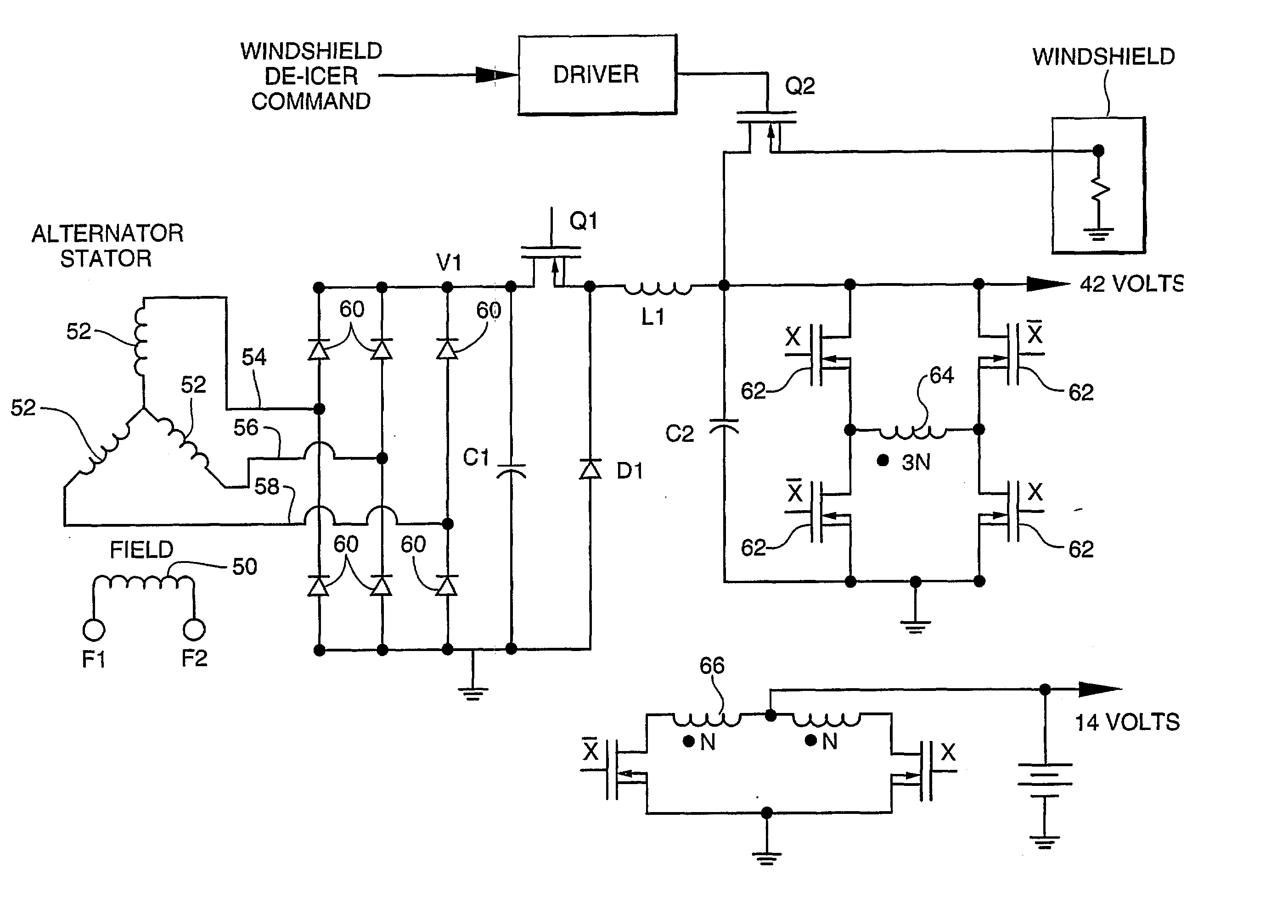
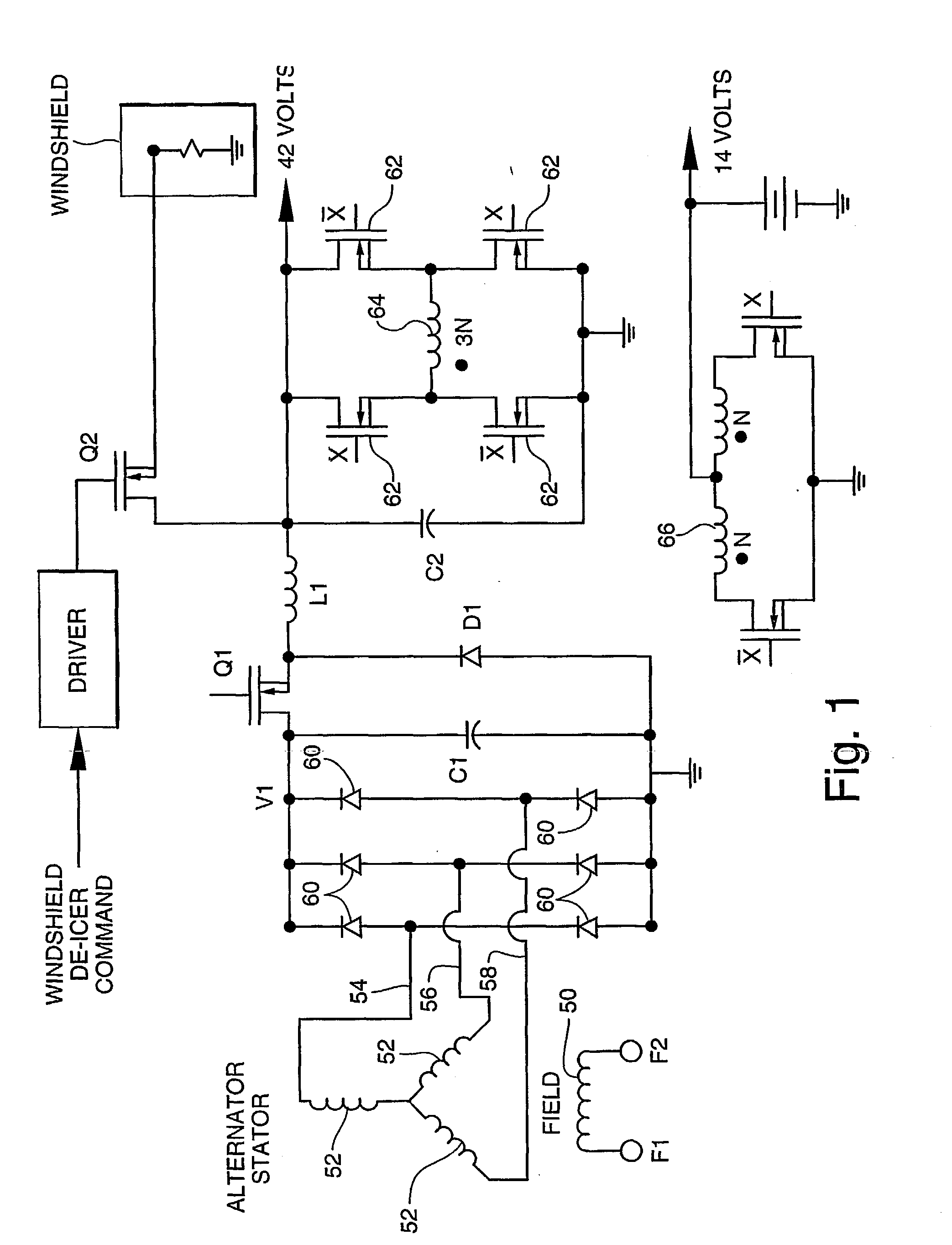
[0034] Referring to FIG. 1, there is shown one embodiment of the alternator system of the present invention. This particular embodiment of the alternator system of the present invention generally comprises an alternator having a rotor (not shown) with rotor field winding 50 and stator windings 52. Current is inputted into field winding 50 via inputs F1 and F2. The output of each of the stator windings 52 is outputted through output leads 54, 56 and 58. As the rotor (not shown) of the alternator rotates, a voltage is induced in the stator windings 52. This voltage is fed through output leads 54, 56 and 58 and is connected to a full wave voltage rectifier formed by six power diodes 60. Such a fill wave voltage rectifier configuration is well known ...


PUM


Abstract

An alternator system (50, 52) that, in one aspect, utilizes a Lundell style alternator that is augmented by power electronic switching components (62) in the output section. In one embodiment, some of these power switching embodiments employ a scaling of stator turns and wire size to achieve the superior performance at higher speeds. The alternator system provides significantly enhanced power capability above idle as compared with classical Lundell alternator systems using Lundell alternators of the same size that are designed with the same power capability at idle. In one preferred dual voltage embodiment, a power switch (semi-conductor) connects the alternator output directly to the low voltage load at low engine speeds and when the power switch is "opened" at higher speeds, the alternator's power is channeled to the higher voltage. In a 14-volt/42-volt dual-voltage system, this arrangement provides triple the alternator's power capability at high speeds as compared to a conventional unenhanced capabilities of the altenator system of the present invention are accomplished without increasing the alternator size or required current capacity and without using high frequency semiconductor power modulation (106).

Description

[0001] The present invention generally relates to an automotive alternator system comprising an alternator having significantly enhanced power capability above idle in comparison with conventional alternators of the same size and which are designed with the same power capability at idle. The technology is particularly applicable to Lundell style alternators and dual voltage systems.RELATED ART[0002] Electronic valve actuation systems require only modest power at low speeds with power growing into the multiple kilowatt range at high engine speeds. One approach to providing the necessary system power at idle and the much higher valve power at high speeds is the classical Lundell technology. A classical Lundell alternator, if optimized for the more modest power required at idle, would only lead to about 1.6 times this power at very high speeds. Even if the system is de-tuned from the optimum power at idle and is designed only to provide the required power at idle and the required power...

Claims


Application Information

Patent Timeline
Patent Type & Authority Applications(United States)
IPC IPC(8): H02M7/12G05F1/613H02J7/14H02M1/00H02M3/156H02M3/28H02M3/337H02M7/06H02P9/14H02P9/30
CPCG05F1/613H02J7/1423H02J7/1492H02M1/32H02M3/1563H02M3/3376H02M7/06H02M2001/0032H02M2001/007H02M2001/009H02P9/305H02P9/307Y02B70/16Y02T10/92H02M1/0032H02M1/007H02M1/009Y02B70/10
Inventor CURTISS, WILLIAM P.
Owner ECOAIR
Why Eureka
Try Eureka