Air tool

a technology of air tools and air-powered tools, which is applied in the direction of electric generator control, magnetic circuit shape/form/construction, magnetic circuit rotating parts, etc., can solve the problems of reducing the electrical output of the generator, reducing the energy of the magnetic circuit, and overheating the coil, so as to achieve less vibration

Inactive Publication Date: 2000-10-17
VOLT AIRE CORP
View PDF33 Cites 38 Cited by
  • Summary
  • Abstract
  • Description
  • Claims
  • Application Information

AI Technical Summary

Benefits of technology

It is an object of the present invention to provide an improved air

Problems solved by technology

This magnetic disorientation results in diminished energy from the magnetic circuit and consequent diminished electrical output from the generator.
Another problem associated with the prior art side-pole arrangement is overheating of the coils 180.
A problem with the air tool of FIG. 13 is that the gooseneck lamp 330, 328 must be frequently adjusted to provide adequate lighting to the work surface.
The gooseneck lamp 330, 328 also undesirably adds to the overall exterior dimensions of the air tool 310 thereby making it more difficult to work in cramped areas.
Another problem with the prior art air motors with integral g

Method used


Image

  • Air tool
  • Air tool
  • Air tool

Examples


Embodiment Construction

An integral air motor generator (IAMG) converts compressed air into rotary torque and electricity. The inventive IAMG utilizes an improved sidepole stator and rotor arrangement.

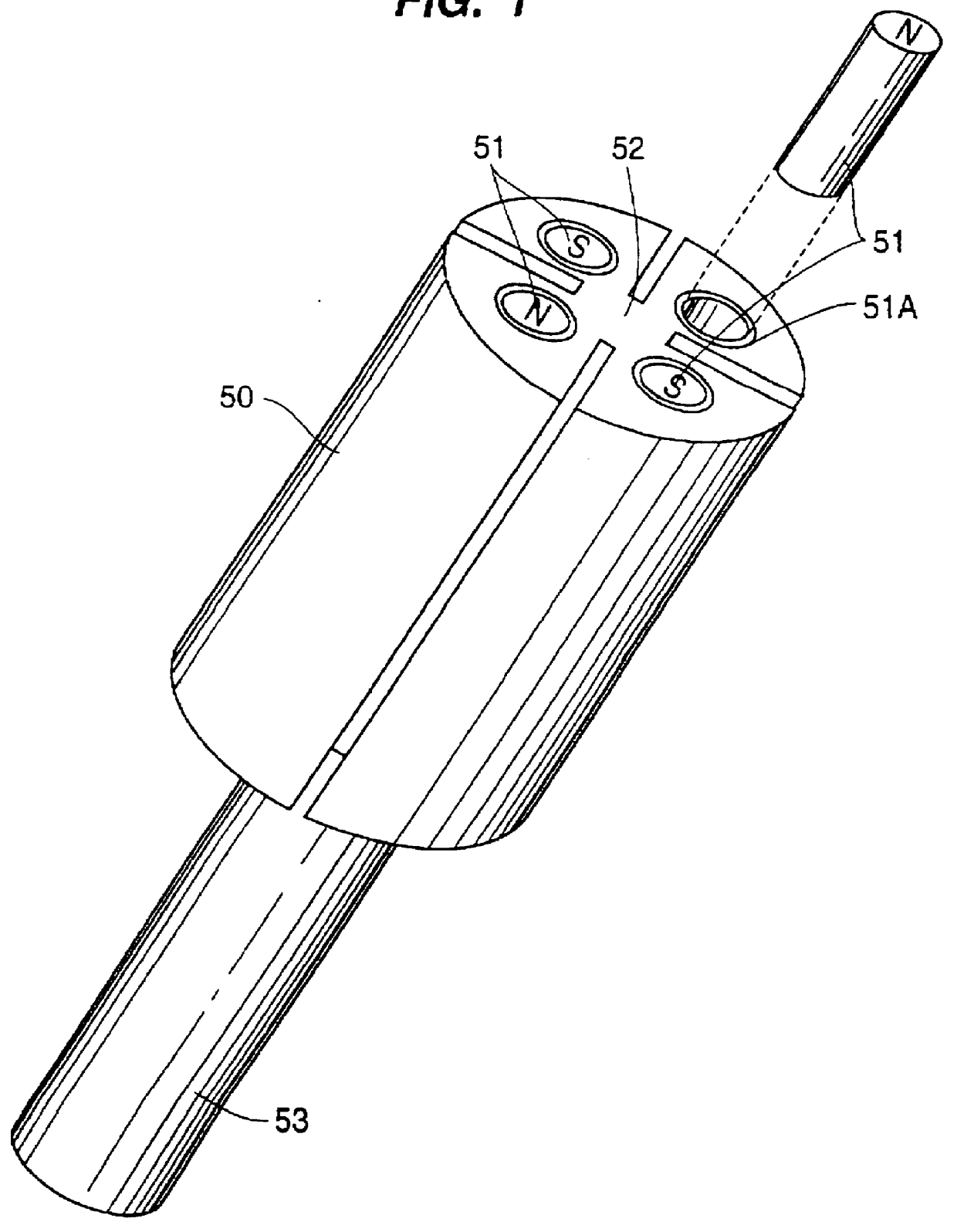
FIG. 1 shows a modified rotor body 50 referred to as a cantilever rotor. The cantilever rotor design improves magnetic induction and decreases the required amount of space, thereby allowing the incorporation of the IAMG into small air powered tools. Significantly improved magnetic induction in the electromagnetic circuit of the generator has been achieved through the incorporation of the magnetic elements 51 into the air motor rotor body 50 (or a segment of the same) in a sidepole arrangement as shown and utilizing nonmagnetic material for the shaft 53 and rotor body 50 (such as stainless steel carbon fiber reinforced thermoplastic or glass fiber reinforced thermoplastic).

An improved permanent magnet 51 is made of a metallic compound consisting of the element neodymium (Symbol Nd, Atomic number, 60, Atomic we...


PUM


Abstract

An improved air tool includes an integrated air motor and electrical generator wherein the stator is positioned on a side of the rotor body opposite the working end of the tool to reduce vibrations transmitted to the stator. The stator is also positioned between the compressed air inlet and the rotor body such that compressed air flows across the stator to prevent overheating of the stator. The air tool includes an indicating circuit connected to the battery charging circuit for indicating a battery charge condition, a battery discharge condition, and a low lubrication condition of the air vanes. A light ring assembly is attached to the working end of the tool housing to provide light at the working end of the tool. Materials chosen for the magnets and the poles of the stator increase the power capability of the electrical generator. An illuminating apparatus for a conventional air tool includes a light ring with integral generator.

Description

BACKGROUND OF THE INVENTIONThe present invention relates in general to improvements to air powered tools and, in particular, to improvements to air powered tools that have an air motor having an integral generator (integrated air motor generator or IAMG).An air tool with an air motor having an integral generator is disclosed in U.S. Pat. No. 4,678,922 issued on Jul. 7, 1987 to the inventor of the present invention. U.S. Pat. No. 4,678,922 is hereby incorporated by reference. FIG. 12 shows the side-pole arrangement of the air motor and integral generator of the '922 patent. As shown in FIG. 12, the side-pole arrangement includes a bearing 139 at the working end of the tool, a bearing end plate 178, an insulating ring 142, coils 180, a magnet rotor 174 having magnets 176, an air chamber 134, a rotor shaft 146, a rotor body 148, fins 150, a bearing end plate 142, a bearing 154 and a retaining ring 156.In the side-pole arrangement of FIG. 12, the magnet rotor 174 and coils 180 are posit...

Claims


Application Information

Patent Timeline
IPC IPC(8): B23B31/02B25F5/00B25F5/02F01D15/00F01D15/06F03D9/00H02K7/14H02K1/27H02K7/18H02K9/22H02K21/12H02K21/24H02K5/12B25B23/18B25H1/00
CPCB23B31/02B25F5/00B25F5/021B25H1/0092F01D15/06F03D9/00F03D9/002H02K1/2713H02K1/2793H02K7/145H02K7/18H02K7/183H02K9/22H02K21/24B25B23/18Y02E10/725H02K5/12F03D9/25Y02E10/72H02K9/227H02K9/223H02K1/2795
Inventor LEININGER, JON J.
Owner VOLT AIRE CORP
Why Eureka
Try Eureka