

Simulated Organ Device
- Summary
- Abstract
- Description
- Claims
- Application Information
AI Technical Summary
Benefits of technology
Problems solved by technology
Method used
Image

Examples
first embodiment
A. First Embodiment
A-1. Configuration of Liquid Ejecting Apparatus
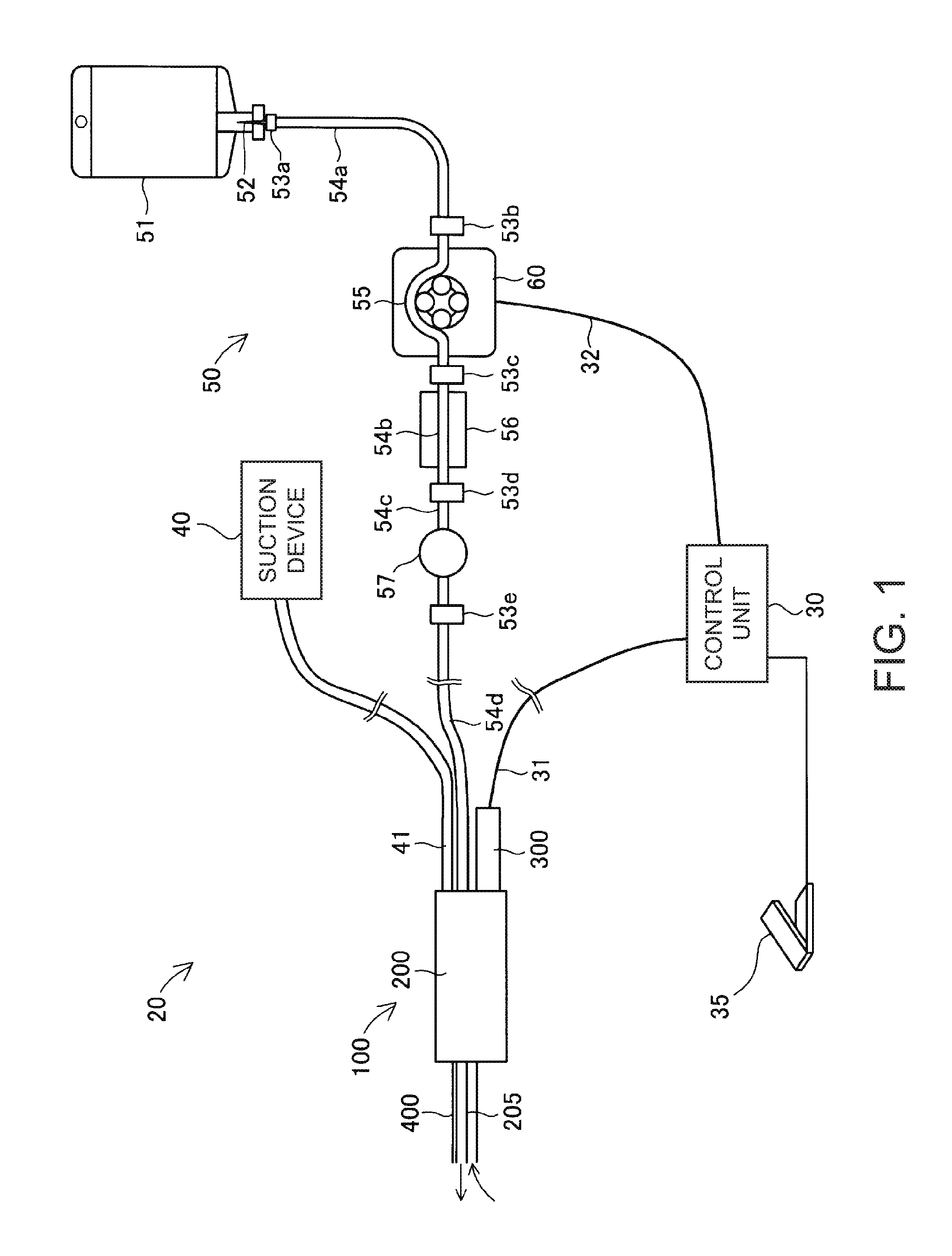
[0029]FIG. 1 schematically illustrates a configuration of a liquid ejecting apparatus 20. The liquid ejecting apparatus 20 is a medical device used in medical institutions, and has a function to excise a lesion by ejecting a liquid to the lesion.
[0030]The liquid ejecting apparatus 20 includes a control unit 30, an actuator cable 31, a pump cable 32, a foot switch 35, a suction device 40, a suction tube 41, a liquid supply device 50, and a handpiece 100.
[0031]The liquid supply device 50 includes a water supply bag 51, a spike needle 52, first to fifth connectors 53a to 53e, first to fourth water supply tubes 54a to 54d, a pump tube 55, a clogging detection mechanism 56, and a filter 57. The handpiece 100 includes a nozzle unit 200 and an actuator unit 300. The nozzle unit 200 includes an ejecting tube 205 and a suction pipe 400.
[0032]The water supply bag 51 is made of a transparent synthetic resin, and the inside there...
second embodiment
B. Second Embodiment
[0051]FIG. 7 is a view for describing a simulated organ device 600 according to a second embodiment. Compared to the simulated organ device 500 according to the first embodiment, the simulated organ device 600 according to the second embodiment adopts a different configuration which includes a plurality of simulated blood vessels 614A, 614B, and 614C, and a plurality of hydraulic pressure adjustment mechanisms 620A, 620B, and 620C.
[0052]The respective simulated blood vessels 614A, 614B, and 614C are the same as the simulated blood vessel 514 according to the first embodiment, and the respective hydraulic pressure adjustment mechanisms 620A, 620B, and 620C are the same as the hydraulic pressure adjustment mechanism 520 according to the first embodiment. Similarly to the first embodiment, one end side of the respective simulated blood vessels 614A, 614B, and 614C are sealed with respective sealing materials 630A, 630B, and 630C. Similarly to the first embodiment, t...
third embodiment
C. Third Embodiment
[0054]FIG. 8 is a view for describing a simulated organ device 700 according to a third embodiment. Compared to the simulated organ device 600 according to the second embodiment, the simulated organ device 700 according to the third embodiment has a different configuration in which a plurality of the simulated blood vessels 614A, 614B, and 614C merge into one on the other end side, and in which one hydraulic pressure adjustment mechanism 520 is disposed in the merged portion. The remaining configurations are the same as those according to the second embodiment. The hydraulic pressure adjustment mechanism. 520 is the same as the hydraulic pressure adjustment mechanism 520 according to the first embodiment.
[0055]Similarly to the second embodiment, the simulated organ device 700 configured as described above can adjust the adhesion between the simulated parenchyma and the simulated blood vessels 614A, 614B, and 614C. In particular, in the simulated organ device 700 a...
PUM
 Abstract
Description
Claims
Application Information