Single event latchup (SEL) current surge mitigation

a single event and current surge technology, applied in the direction of emergency protective circuit arrangements, emergency protective arrangements for limiting excess voltage/current, instruments, etc., can solve the problems of sel being destructive, damage or destroy the integrated circuit, and the operation of the integrated circuit can be temporarily or permanently disrupted, etc., to achieve the effect of false alarm ra

Active Publication Date: 2017-02-02
HARRIS CORP
View PDF4 Cites 18 Cited by
  • Summary
  • Abstract
  • Description
  • Claims
  • Application Information

AI Technical Summary

Problems solved by technology

The operation of integrated circuits can be temporarily or permanently disrupted due to single event effects associated with exposure to energetic particles such as protons and heavy ions.
If this parasitic SCR circuit is triggered, the resulting SEL current may damage or destroy the integrated circuit, unless the SEL current is properly limited or promptly removed.
Accordingly, the SEL can be destructive if the resulting current draw within an integrated circuit is sufficient to damage the junction and or a wire bond which is associated with the device.
SEL can cause latent internal damage that can subtlety degrade device reliability, which discourages the use of SEL-prone parts even if obvious device damage is not apparent.
Accordingly, the use of integrated circuits which are vulnerable to SEL is severely restricted in applications such as space programs where exposure to energetic ions is anticipated.
However, the fact that an ion impacts a detector does not provide information about ions hitting sensitive areas and causing a single event latchup.
But a simple current-limiting regulator does not address the problem of how to decide when a given current surge corresponds to SEL, nor does it solve the problem of SEL currents that are less than the maximum operating current for a device.
However, this approach is impractical when utilizing existing commercial off-the-shelf integrated circuit devices in which power cannot be internally subdivided.
It also fails to address the importance of extremely fast detection of SEL events and fast response times, which are key for purposes of preventing damage to electronic circuits when SEL does occur.

Method used


Image

  • Single event latchup (SEL) current surge mitigation
  • Single event latchup (SEL) current surge mitigation
  • Single event latchup (SEL) current surge mitigation

Examples


Embodiment Construction

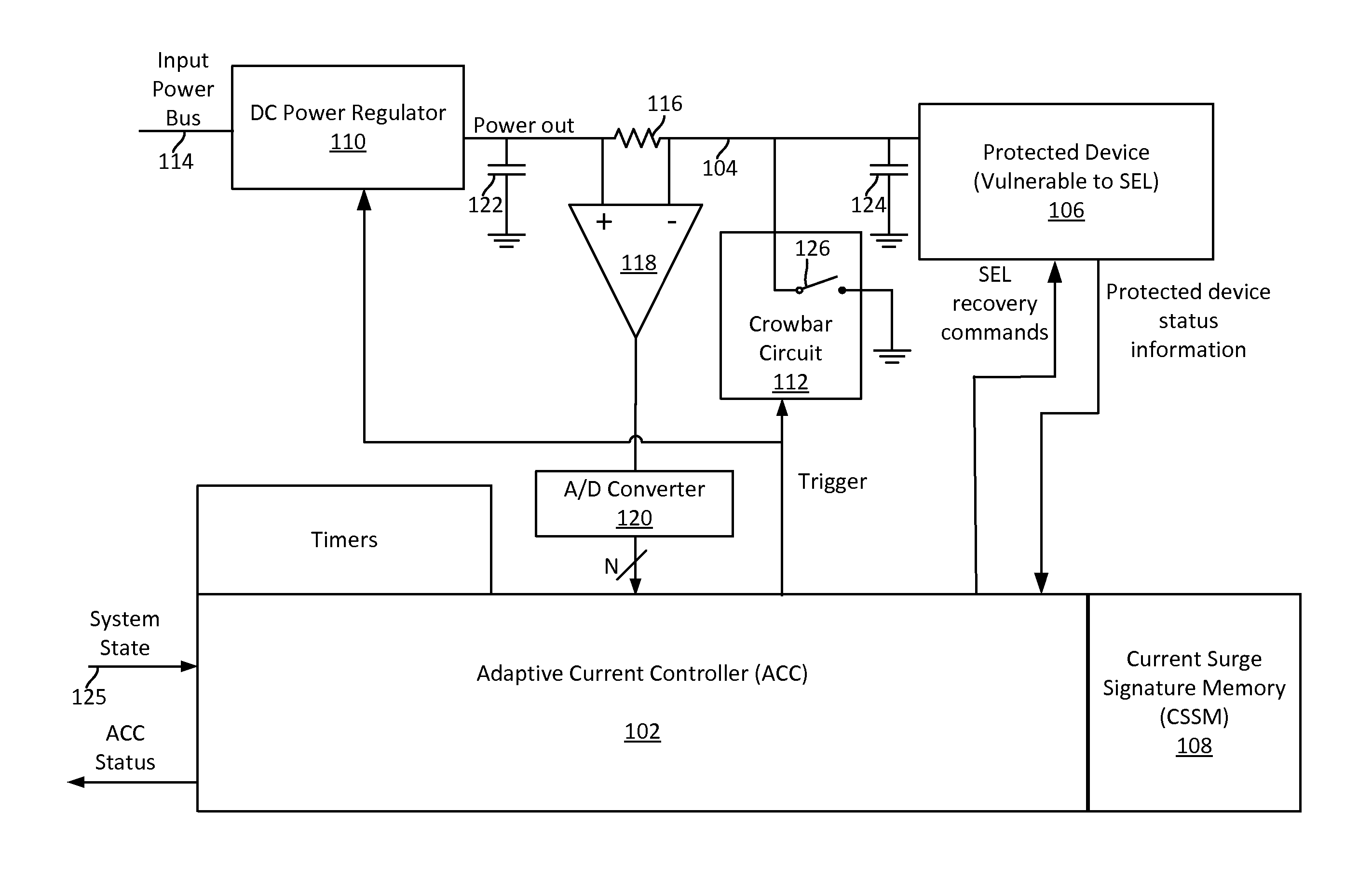
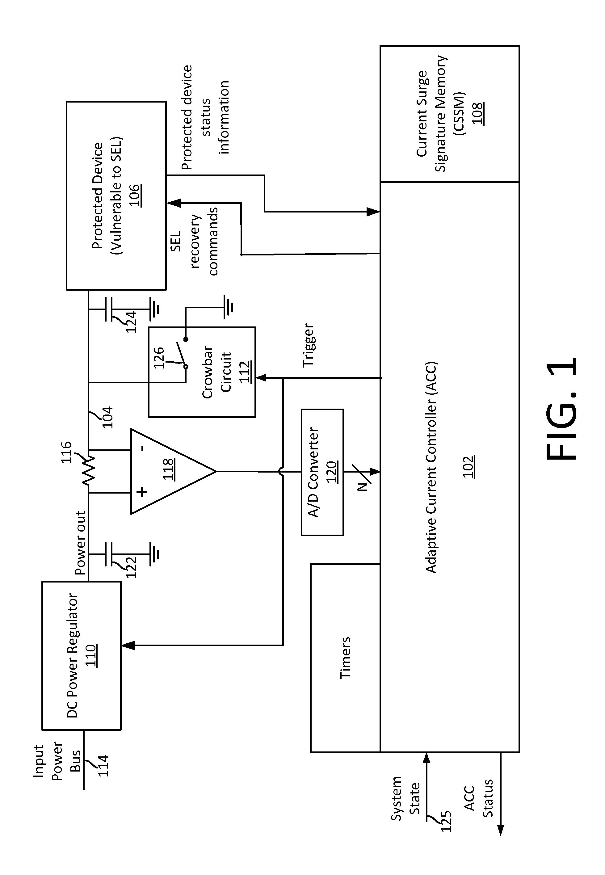
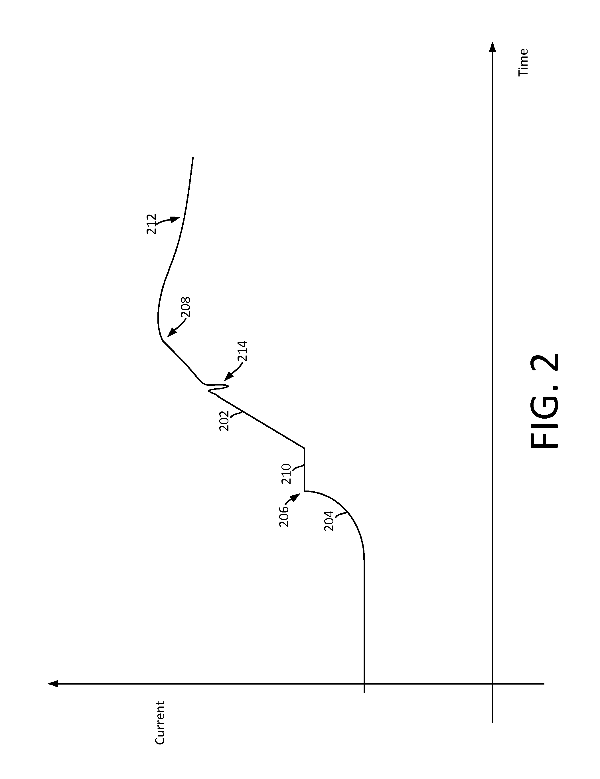
[0019]The invention is described with reference to the attached figures. The figures are not drawn to scale and they are provided merely to illustrate the instant invention. Several aspects of the invention are described below with reference to example applications for illustration. It should be understood that numerous specific details, relationships, and methods are set forth to provide a full understanding of the invention. However, the invention can be practiced without one or more of the specific details or with other methods. In other instances, well-known structures or operation are not shown in detail to avoid obscuring the invention. The invention is not limited by the illustrated ordering of acts or events, as some acts may occur in different orders and / or concurrently with other acts or events. Furthermore, not all illustrated acts or events are required to implement a methodology in accordance with the invention.

[0020]Reference throughout this specification to features, ...


PUM


Abstract

Method and system for Single Event Latchup (SEL) current surge mitigation involves monitoring data signals for a protected device and deriving from them a detected signature comprised of one or more detected signature vector components. The detected signature vector components are compared to previously stored signature vector components. Based on the comparing, the system selectively differentiates between the occurrence of standard power surges associated with normal operation of the protected device, and a non-standard current surge which requires cycling power of the protected device for continued proper functioning of the protected device.

Description

BACKGROUND OF THE INVENTION[0001]Statement of the Technical Field[0002]The inventive arrangements relate to single event latchup (SEL) current surge mitigation techniques, and more particularly to adaptive methods and systems that facilitate the use of certain types of electronic devices in environments where they would otherwise be vulnerable to power surge problems.DESCRIPTION OF THE RELATED ART[0003]The operation of integrated circuits can be temporarily or permanently disrupted due to single event effects associated with exposure to energetic particles such as protons and heavy ions. These events can occur through various mechanisms including one which is known as single event latch-up (SEL). An SEL event can occur when a dense track of electron-hole pairs produced in a silicon die by an energetic ion triggers certain parasitic circuit elements that form a Silicon Controlled Rectifier (SCR) in the integrated circuit. If this parasitic SCR circuit is triggered, the resulting SEL ...

Claims


Application Information

Patent Timeline
Patent Type & Authority Applications(United States)
IPC IPC(8): H02H9/02H02H3/087
CPCH02H3/087H02H9/02H02H3/05H02H3/10H02H5/005G01R31/31816
Inventor VAIL, DAVIDDIEDLING, DAVIDBOESCH, WILLIAMBRUCKMEYER, JOSHUA P.
Owner HARRIS CORP
Why Eureka
Try Eureka