Extremity tourniquet with locking buckle

a technology of tourniquets and buckles, applied in the field of tourniquets, can solve the problems of ineffective fine circumference adjustment mechanisms, slow application times, increased initial blood loss, etc., and achieve the effect of increasing the tension of the tourniquets

Active Publication Date: 2017-02-09
THE SEABERG
View PDF5 Cites 23 Cited by
  • Summary
  • Abstract
  • Description
  • Claims
  • Application Information

AI Technical Summary

Benefits of technology

[0025]Application of an extremity tourniquet according to the disclosure herein can provide assurance of proper constriction of a large limb such as a patient's thigh, as application of the tourniquet involves first the step of fastening an elongate member of the tourniquet around the affected limb with a predetermined amount of tension, as regulated by a tension-measuring and setting buckle. The tension in the tourniquet is then increased by the use of a fine adjustment mechanism, and the user can determine with confidence whether a second tourniquet should be applied, as the force-controlled buckle provides assurance that a first tourniquet has been applied in a manner that assures proper function of the first tourniquet.

Problems solved by technology

Three common shortfalls of previously known emergency tourniquets are:
1) Too much slack remains in the loop after Gross Circumference adjustment, leading to ineffectiveness of the Fine Circumference adjustment mechanism. This can result in slower application times, increased initial blood loss, or complete ineffectiveness.
2) The securement devices associated with the Gross Circumference adjustment mechanism may accidently loosen, fail, or be released after control of a hemorrhage is achieved, resulting in resumed or continued bleeding. This may be exacerbated by the fact that the Fine Circumference adjustment places an increasing force on the Gross Circumferential fastener, making the securement device more prone to failure.
3) The user is confused as to whether two tourniquets are necessary. Currently large thighs often require two tourniquets. However, the user does not know whether a first tourniquet has too much slack in it or whether it is functioning as intended. As a result, the user is not sure whether to remove and reapply the first one or put on a second.

Method used


Image

  • Extremity tourniquet with locking buckle
  • Extremity tourniquet with locking buckle
  • Extremity tourniquet with locking buckle

Examples


Embodiment Construction

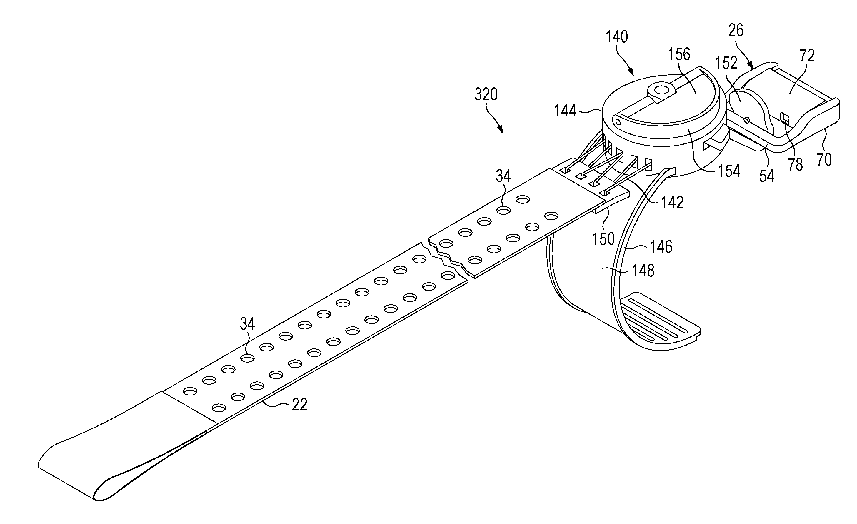
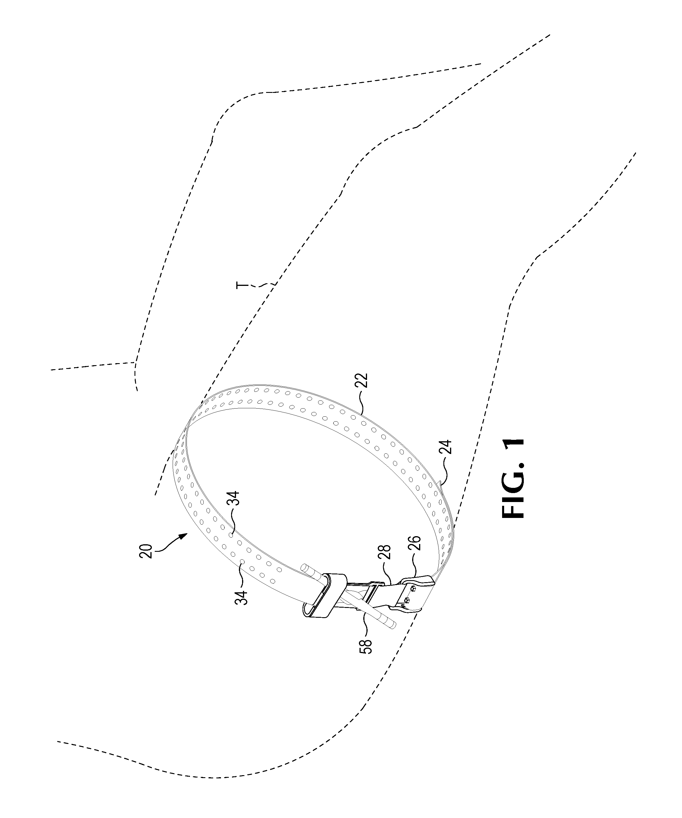
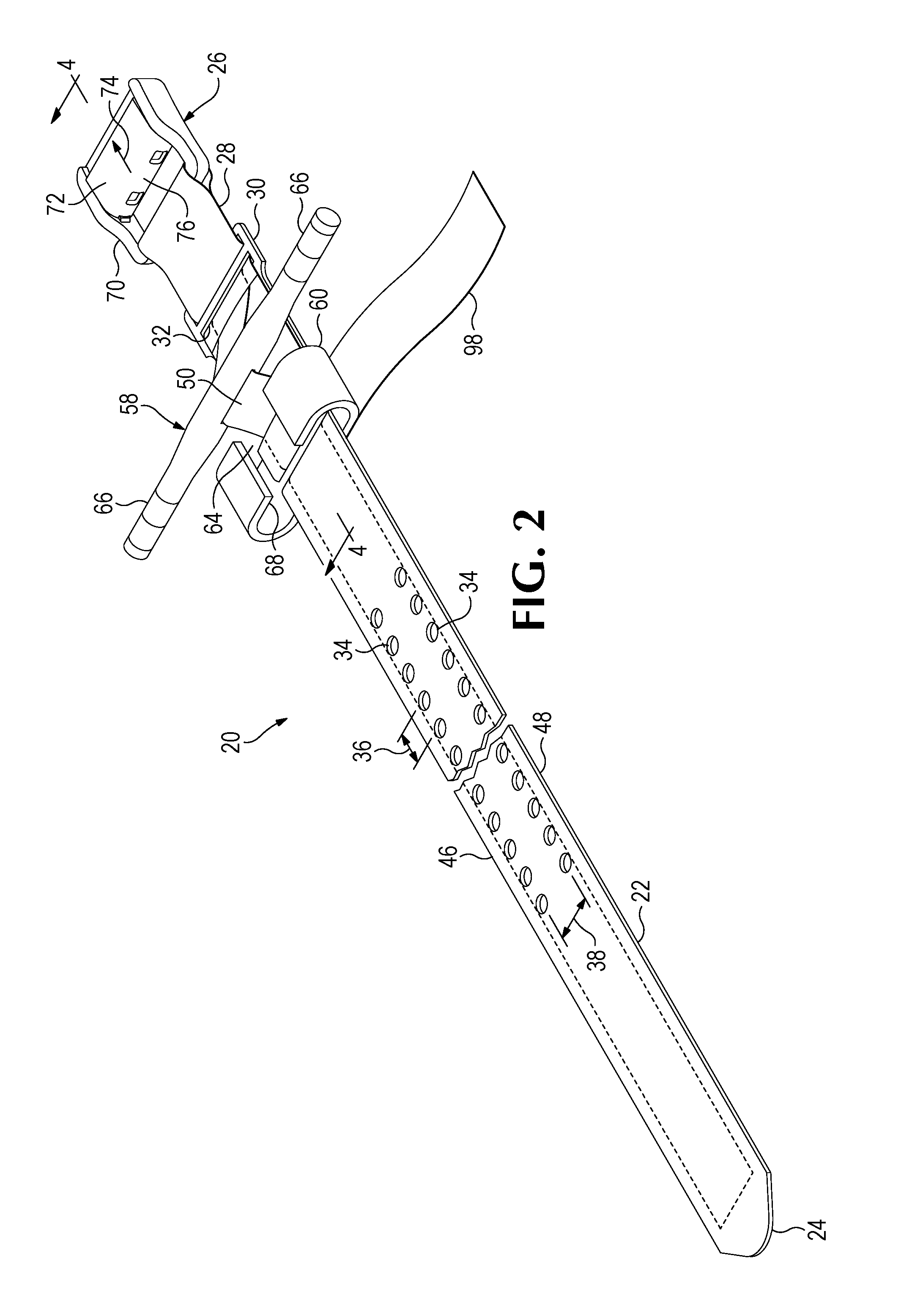
[0060]Referring to the drawings that form a part of the disclosure herein, a tourniquet 20 which is a first embodiment of the emergency extremity tourniquet disclosed herein is shown in FIGS. 1-9. In FIG. 1, the tourniquet 20 is shown in place on a patient's thigh T. As shown somewhat more clearly in FIGS. 2 and 3, the tourniquet 20 includes an elongate strap 22 having a first, or outer, end 24 and a buckle 26 permanently attached to its opposite, second, or inner end 28 as by a loop 29 of the strap fitted around a part of the buckle 26. A backing plate 30, of a suitably strong plastic resin or of sheet metal, for example, may be provided, and the strap 22 may be threaded through a pair of slots 32, provided at the ends of the backing plate 30, as shown in FIGS. 4 and 5.

[0061]As used herein, the term “permanently attached” means that removal and reattachment are not easily accomplished by a user and cannot be accomplished readily without the use of equipment similar to that needed f...


PUM


Abstract

A tourniquet for application to a patient's limb in an emergency situation, and a method for its application. The tourniquet includes a tension-sensing mechanism used to establish a baseline tension in a loop around an injured limb, and a tension-increasing mechanism to reduce the circumference of the loop and tighten the tourniquet as required beyond the baseline tension. The tension-sensing mechanism may be incorporated in a buckle in which when sufficient tension is developed in the loop a pin protrudes to engage and maintain tension in a strap member which is part of the loop. A latch may be incorporated in the buckle to keep it in a condition in which the pin protrudes to engage the strap and maintain the baseline tension. A release tab operable to release the latch is located where it is protected against inadvertent operation.

Description

CROSS-REFERENCE TO RELATED APPLICATIONS[0001]This application is a continuation-in-part of U.S. patent application Ser. No. 14 / 097,018, filed Dec. 4, 2013, entitled “Reversibly Engaged Force-Controlled Buckle and Pelvic Ring Support Device Incorporating Such A Buckle” and claims the benefit of U.S. Provisional Patent Application Ser. No. 61 / 733,058 filed Dec. 4, 2012. This application is also a continuation-in-part of U.S. patent application Ser. No. 14 / 324,672, entitled Extremity Tourniquet, filed Feb. 4, 2015, and claims the benefit of the filing date of U.S. Provisional Patent Application Ser. No. 61 / 935,566, filed Feb. 4, 2014.BACKGROUND OF THE INVENTION[0002]The present application relates to tourniquets, and particularly to emergency tourniquets intended for rapid application to a patient's limb, such as a severely injured leg or arm, to minimize or stop blood loss.[0003]Most modern emergency tourniquets are applied by using the following three similar steps:[0004]1) Placement...

Claims


Application Information

Patent Timeline
Patent Type & Authority Applications(United States)
IPC IPC(8): A61B17/132A44B11/25A44B11/26A44B11/20A44B11/06
CPCA61B17/1325A61B17/132A61B17/1322A44B11/2592A44B11/065A44B11/266A44B11/20A61F5/0102Y10T24/407A44B11/125A44B11/223A61F5/30A61F5/34
Inventor HOPMAN, LANCE DBATDORF, ERIC E
Owner THE SEABERG
Why Eureka
Try Eureka