Transparent material light-emitting module with two reflection faces

a technology of transparent material and light-emitting module, which is applied in the field of light-emitting, can solve the problems of increasing the overall size, requiring a certain amount of space along the optical axis, and the exit face cannot serve as a styling face, and achieves the effects of reducing the number of reflections, and reducing the size of the overall beam

Active Publication Date: 2017-02-09
VALEO VISION SA
View PDF10 Cites 5 Cited by
  • Summary
  • Abstract
  • Description
  • Claims
  • Application Information

AI Technical Summary

Benefits of technology

[0028]The measures of the invention are beneficial in that they make it possible to produce a light-emitting module that is particularly compact in the direction of the optical axis, i.e. the longitudinal axis of the vehicle. The use of a dioptric bender, i.e. with the first reflection face reflecting the rays by the principle of total internal reflection, is notably advantageous in that it renders the module more tolerant to focusing defects. Moreover, the use of a plurality of collimators on the entry face makes it possible to compose the light beam and therefore confers great flexibility in the implementation of different functions. Moreover, the module has a common exit face, which has advantages in terms of aesthetics and the precision of the total beam resulting from the addition of the beams produced by the various collimators.

Problems solved by technology

However, it has the disadvantage that it requires a certain amount of space along the optical axis.
Moreover, because of its shape the exit face cannot serve as a styling face, i.e. one directly visible from the outside of the lighting device including the module.
It is therefore necessary to provide an additional styling surface, which also increases the overall size.

Method used


Image

  • Transparent material light-emitting module with two reflection faces
  • Transparent material light-emitting module with two reflection faces
  • Transparent material light-emitting module with two reflection faces

Examples


Embodiment Construction

[0037]In the following description, relative terms such as “top”, “upper”, “bottom”, “lower”, “front” and “rear” are to be understood in relation to the orientation of the light-emitting module 2 as shown in the figures, it being understood that in practice the light-emitting module 2 can assume other orientations.

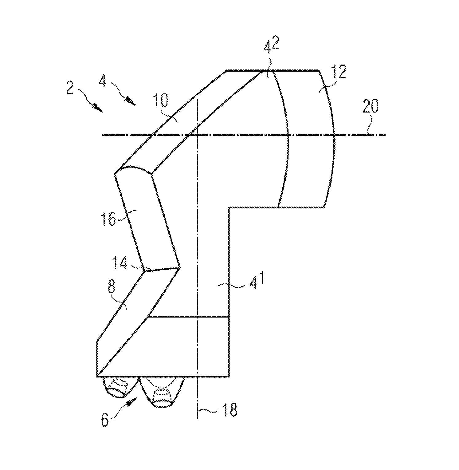
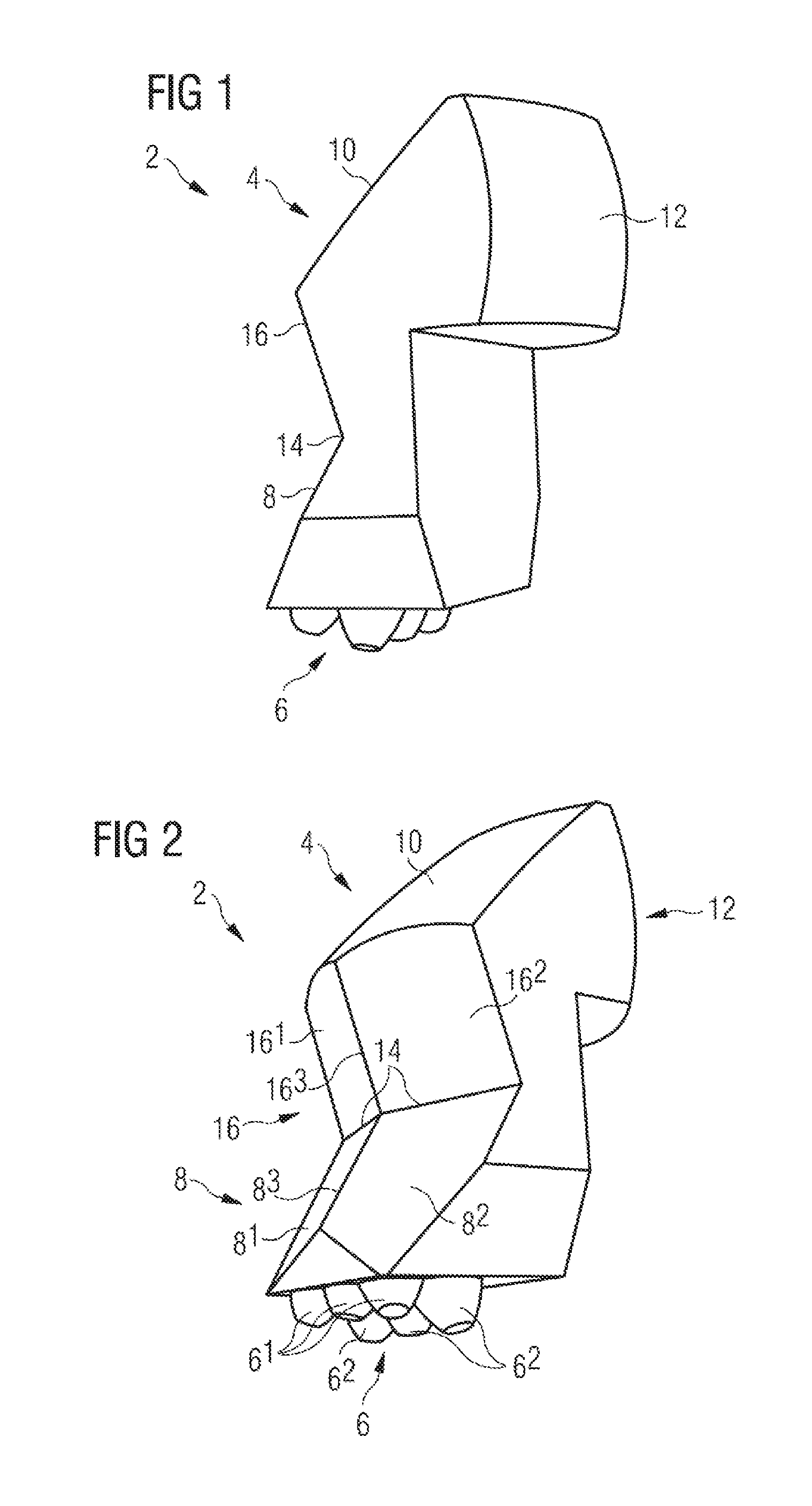
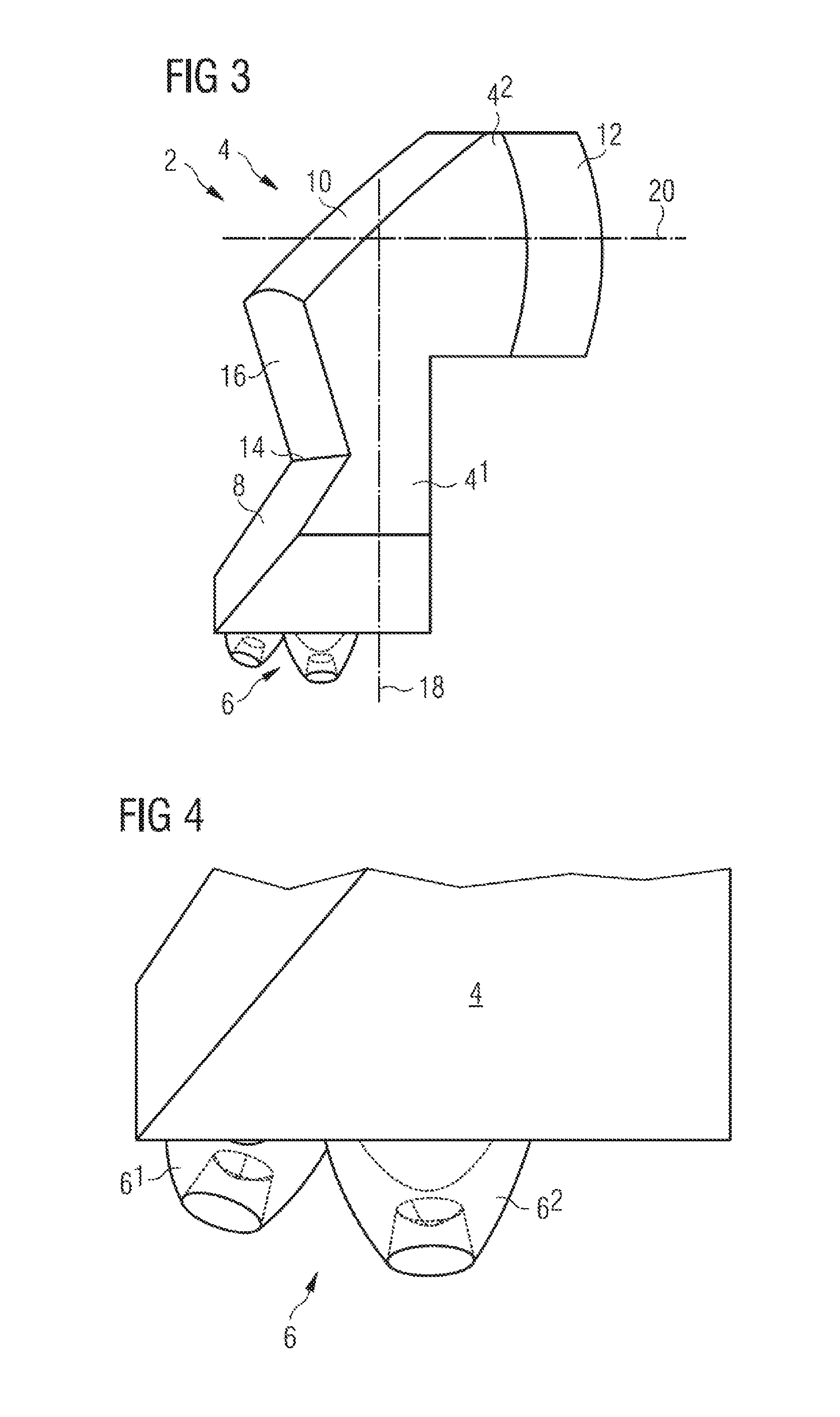
[0038]FIGS. 1 to 4 illustrate a light-emitting module 2 in accordance with the invention. The light-emitting module 2 essentially comprises a body 4 and light sources (not represented).

[0039]The body 4 is made mainly, preferably totally, from a transparent or translucent material. That material may be glass or preferably plastic, such as polycarbonate (PC) in particular.

[0040]The body 4 includes an entry face 6 for the light produced by the light sources. The latter may be light-emitting diodes or of the laser type. The body 4 also includes a first reflection face 8 intended to reflect only some of the rays, a second reflection face 10, intended to reflect virtually all of...


PUM


Abstract

A light-emitting module, notably for a motor vehicle, including a translucent or transparent material body having an entry face for light rays produced by one or more light sources, a first reflection face with an edge for cutting off the rays coming from the entry face, a second reflection face for reflecting toward the exit face rays coming from the first reflection face, and an exit face for the light rays in an exit beam along an optical axis of the light emitting module. The invention also relates to a headlight including at least one such light-emitting module.

Description

CROSS-REFERENCE TO RELATED APPLICATIONS[0001]This application claims priority to the French application 1557584, filed Aug. 6, 2015, which application is incorporated herein by reference and made a part hereof.BACKGROUND OF THE INVENTION[0002]1. Field of the Invention[0003]The invention relates to the field of lighting, notably lighting for a motor vehicle. The invention also relates to a headlight including a module of this kind.[0004]2. Description of the Related Art[0005]The published patent document FR 3 010 772 A1 discloses a lighting module with a transparent material body having an entry face for the light produced by one or more light sources, a reflection face with a cut-off edge and an exit face of the rays. The entry face includes a cavity formed at one end of the module, in the transparent material, and delimited by a circular surface forming a diopter adapted to deflect the incoming rays towards the exterior and peripheral surface of the body. The rays are then reflecte...

Claims


Application Information

Patent Timeline
Patent Type & Authority Applications(United States)
IPC IPC(8): F21S8/10G02B27/30
CPCF21S48/1388G02B27/30F21Y2115/10F21S48/115F21S48/1225F21S41/141F21S41/285F21S41/322F21S41/36F21W2102/00F21S41/148F21S41/24F21S41/27F21S41/365G02B6/00
Inventor GROMFELD, YVES
Owner VALEO VISION SA
Why Eureka
Try Eureka