Lens arrays configurations for improved signal performance

a technology of arrays and lenses, applied in the direction of parallel-plate/lens fed arrays, antennas, antenna details, etc., can solve the problems of limiting the utility of the device, limiting the relative angle of reception/transmission of adjacent feeds, and affecting the manufacture of large lenses

Active Publication Date: 2017-02-09
MATSING PTE
View PDF5 Cites 22 Cited by
  • Summary
  • Abstract
  • Description
  • Claims
  • Application Information

AI Technical Summary

Benefits of technology

[0011]Various objects, features, aspects and advantages of the inventive subject matter will become more apparent from the following detailed description of preferred embodiments, along with the accompanying drawing figures in which like numerals represent like components.

Problems solved by technology

Increasing capacity beyond this can be accomplished by decreasing the beam width along the azimuth plane, however this restricts the utility of the device.
An alternative is to increase the size of the Luneburg lens, however this approach rapidly encounters issues with the manufacturability of large lenses and the practical issues introduced by the size and weight of the larger lens.
Unfortunately, such an arrangement greatly restricts the relative angles of reception / transmission of adjacent feeds due to intersection of the transmitted or received signal with a portion of an adjacent lens.
Such antenna arrays are also subject to the generation of undesirable grating lobes as a result of rapid decreases in field amplitudes between adjacent lenses.

Method used


Image

  • Lens arrays configurations for improved signal performance
  • Lens arrays configurations for improved signal performance
  • Lens arrays configurations for improved signal performance

Examples


Embodiment Construction

[0023]Throughout the following discussion, numerous references will be made regarding servers, services, interfaces, engines, modules, clients, peers, portals, platforms, or other systems formed from computing devices. It should be appreciated that the use of such terms is deemed to represent one or more computing devices having at least one processor (e.g., ASIC, FPGA, DSP, x86, ARM, ColdFire, GPU, multi-core processors, etc.) configured to execute software instructions stored on a computer readable tangible, non-transitory medium (e.g., hard drive, solid state drive, RAM, flash, ROM, etc.). For example, a server can include one or more computers operating as a web server, database server, or other type of computer server in a manner to fulfill described roles, responsibilities, or functions. One should further appreciate the disclosed computer-based algorithms, processes, methods, or other types of instruction sets can be embodied as a computer program product comprising a non-tra...


PUM


Abstract

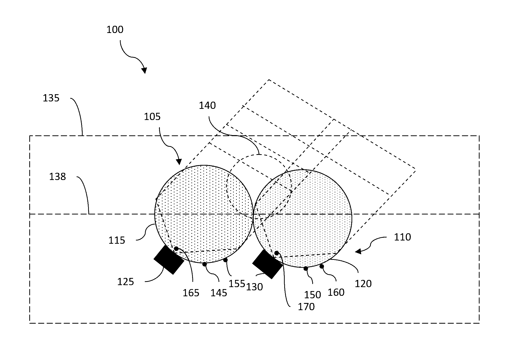
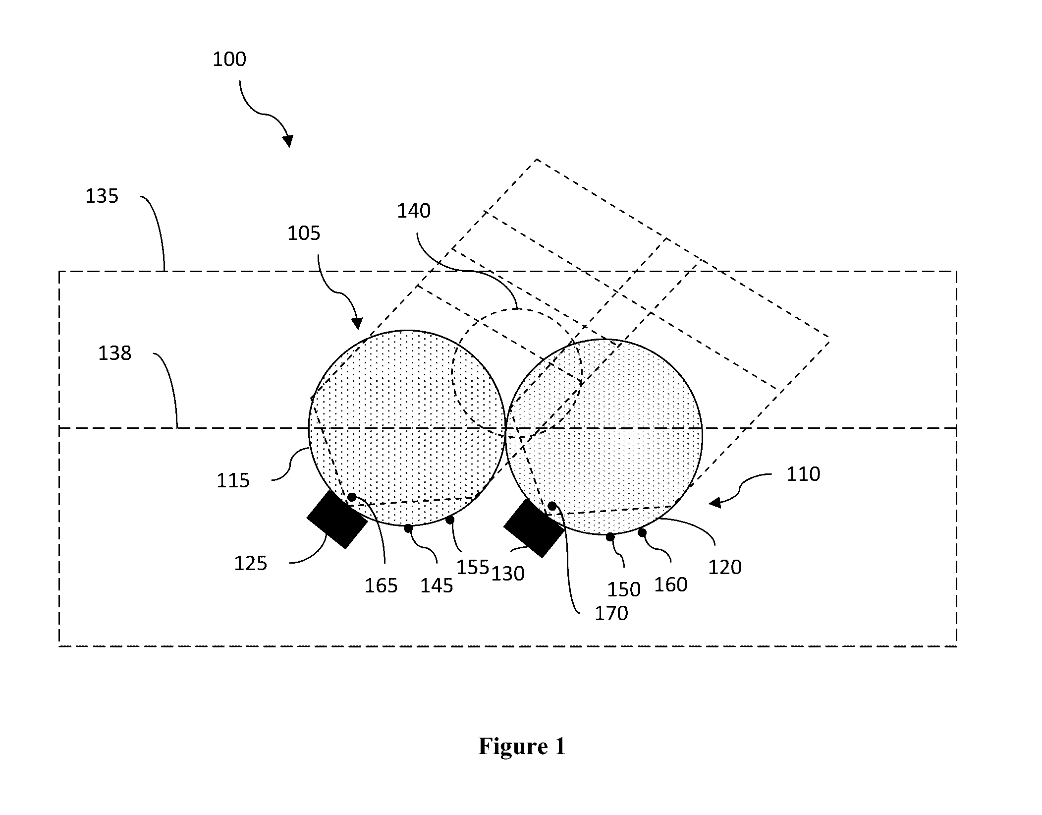
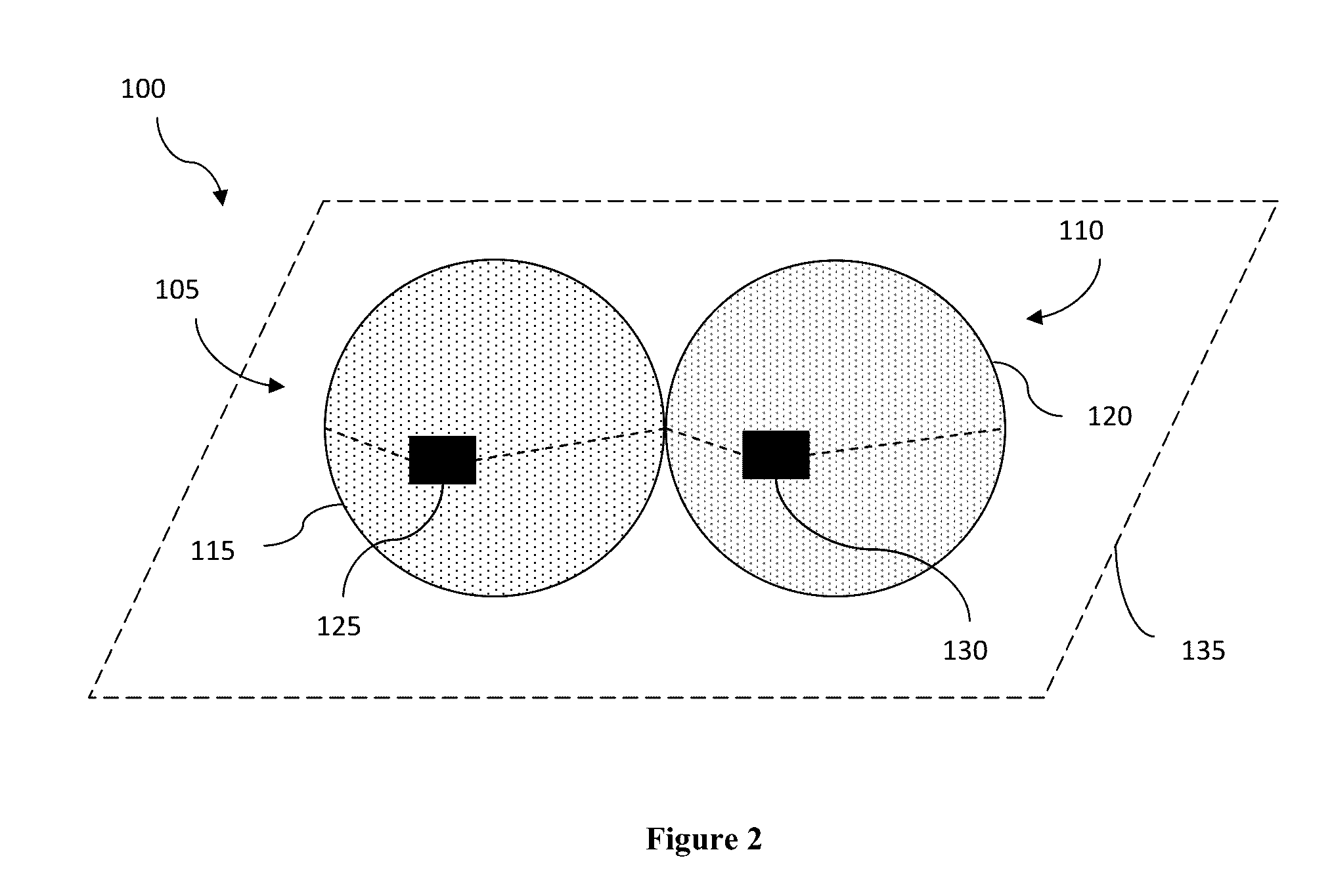
A lens elements array comprises at least two lens elements aligned along an alignment axis. Each lens element includes a spherical lens and a feed element. The feed elements are tilted such that the RF signals generated by the feed elements have major axes form an angle (preferably between 5° and)30° other than a perpendicular angle with respect to the alignment axis. The combined RF signals produced collectively by these feed elements have amplitude that has minimal dips across the array. The feed elements that are farther away from the center of the array have higher levels of tilts than the feed elements that are closer to the center of the array.

Description

[0001]This application claims the benefit of U.S. provisional application No. 62 / 201,472 filed Aug. 5, 2015. This and all other referenced extrinsic materials are incorporated herein by reference in their entirety. Where a definition or use of a term in a reference that is incorporated by reference is inconsistent or contrary to the definition of that term provided herein, the definition of that term provided herein is deemed to be controlling.FIELD OF THE INVENTION[0002]The field of the invention is radio frequency antenna technology.BACKGROUND[0003]The following description includes information that may be useful in understanding the present invention. It is not an admission that any of the information provided herein is prior art or relevant to the presently claimed invention, or that any publication specifically or implicitly referenced is prior art.[0004]Radio and microwave frequencies are widely used in wireless communication. Antennae utilized in receiving and sending such si...

Claims


Application Information

Patent Timeline
Patent Type & Authority Applications(United States)
IPC IPC(8): H01Q15/02H01Q1/22H01Q21/00
CPCH01Q15/02H01Q1/2291H01Q21/0031H01Q21/00
Inventor MATITSINE, SERGUEIMATYTSINE, LEONIDDEMARCO, ANTHONY
Owner MATSING PTE
Why Eureka
Try Eureka