Determination of the three-dimensional location of a target viewed by a camera

a three-dimensional location and camera technology, applied in the direction of navigation instruments, using reradiation, instruments, etc., can solve the problems of large surveillance area, small manpower available for surveillance, and inability to counter a detected incursion, so as to improve the accuracy of object location

Active Publication Date: 2011-11-01
LOCKHEED MARTIN CORP
View PDF30 Cites 66 Cited by
  • Summary
  • Abstract
  • Description
  • Claims
  • Application Information

AI Technical Summary

Benefits of technology

[0011]An alternative mode according to this aspect of the invention, for performing close surveillance of a moving object in a region of interest, comprises the steps of additionally observing the region of interest with radar to produce a two-dimensional radar track, including at least range and azimuth, of the object in the region of interest, and providing geospatial coordinates of the location of the radar. This alternative mode also includes the providing of a further map including the altitudes of geospatial coordinate points, at least in the region of interest, together with computed range, azimuth, and elevation from the radar location to each map point. The further map is processed together with the location of the radar track in range and azimuth angle and together with the location of the radar, for producing three dimensional radar object location information. The processed three dimensional radar object location is correlated to the processed three dimensional camera object location, and the information relating the object location, as generated by the radar and the camera, is fused to improve the accuracy of the object location. In one version of this mode, a surveillance craft is guided toward the three-dimensional location.

Problems solved by technology

One of the problems with such surveillance is that the regions under surveillance may be large, and the manpower available to perform the surveillance may be small.
The availability of personnel to counter a detected incursion is a different issue.
When the number of eyes available to perform surveillance or to survey is small, there is the possibility, or even the likelihood, that some incursions will not be noticed.
Even when a large number of eyes is available, the relative infrequency of incursions may lead to momentary inattention, which again can lead to unnoticed incursions.
One disadvantage of this is that some of the sensors might have to be placed on the sovereign territory of another, which might not be possible.
In addition, deploying such sensors over many miles along, and over suitable depth of, a border will be quite expensive.
Also, such sensors have the disadvantage that battery power would be required, and the changing of batteries in a large plurality of sensors scattered over a region in turn requires substantial manpower.
Even if ground proximity sensors were to be deployed, they tend to be susceptible to false alarms such as animal movement (or even to movement of tree roots along the northern border).
Historically, ground proximity sensors have been poor performers.
Additionally, the GSRs available for border surveillance tend to have slow update rates (half a minute to more than a minute per scan), and also limitations in detection of objects with low radial velocity (relative to the radar location).
The two dimensional object location, together with the slow update rate, make radar data somewhat difficult to use for the important task of cueing narrow field of view interrogation cameras to closely observe the target of interest.
In addition, significant limitations to angular resolution and range accuracy result in the detection mode of operation not being as effective as the tracking modes.
Additional limitations of radar border surveillance include possible inability to detect objects through vegetation and under various clutter conditions.
A major disadvantage of radar systems is that they cannot, in general, identify an object.
Indeed, a low-flying bird might give rise to concern, since radar generally cannot determine the shape of an object.
Radar systems undesirably tend to require skilled operators and maintenance personnel.
On the other hand, cameras have a problem similar to that of radar, in that they provide only a two-dimensional (azimuth and elevation) representation of a three-dimensional world.
Another disadvantage of cameras for surveillance use is that the camera can only “see” objects which subtend a substantial portion of the field-of-view.
Yet a further disadvantage of cameras for surveillance is that the video analytics processing, which is well-known processing for detecting motion from frame-to-frame variations in each pixel, tends to require the operator to configure each individual field of view to be monitored so that detected objects can be converted to geospatial coordinates.
This configuration task might take several hours, depending on the operator.

Method used


Image

  • Determination of the three-dimensional location of a target viewed by a camera
  • Determination of the three-dimensional location of a target viewed by a camera
  • Determination of the three-dimensional location of a target viewed by a camera

Examples


Embodiment Construction

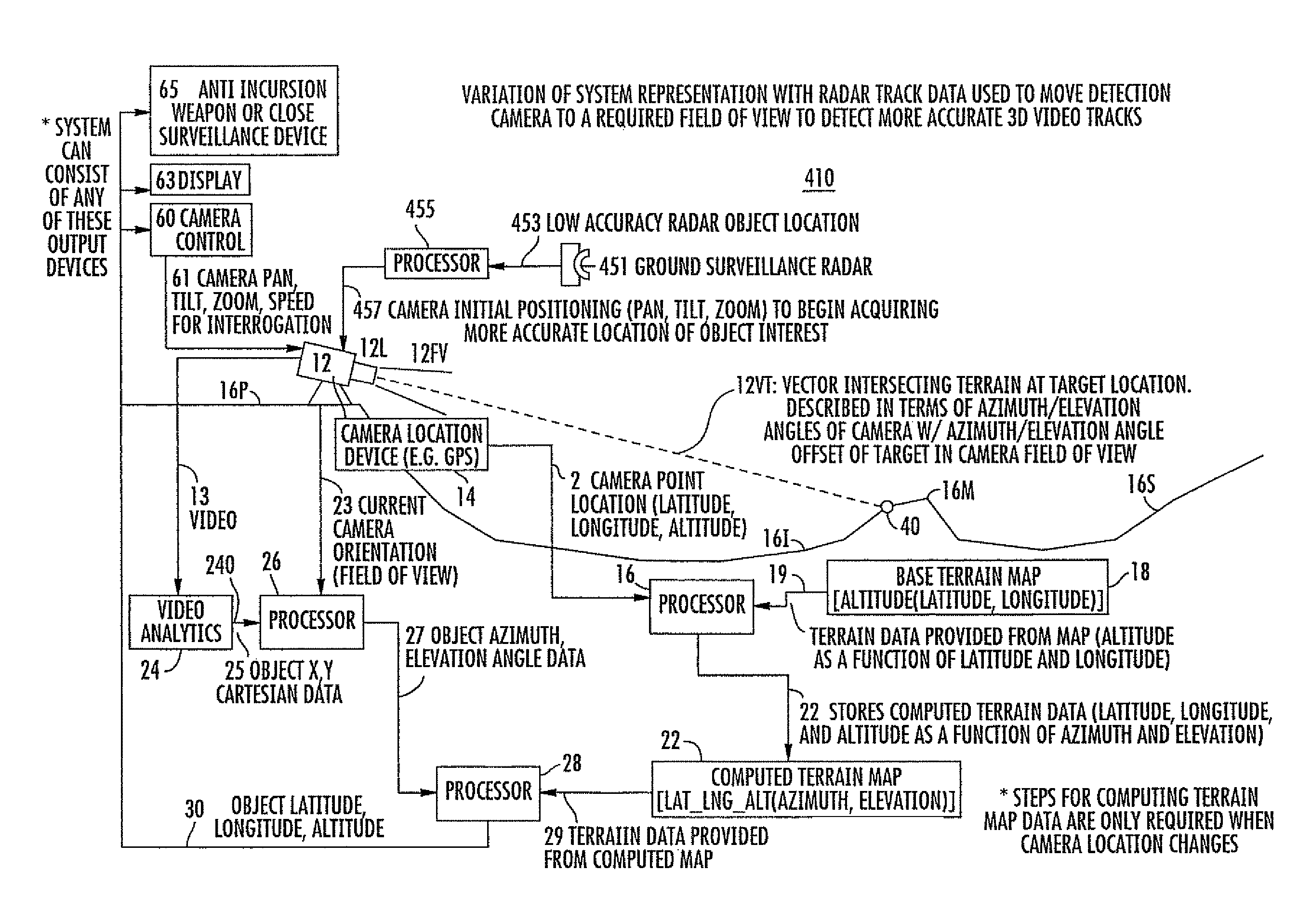
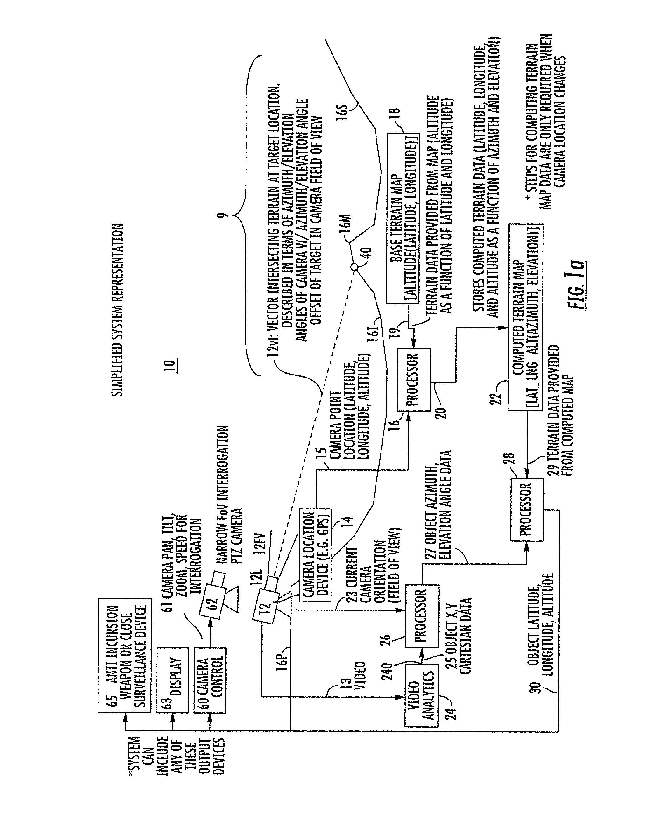
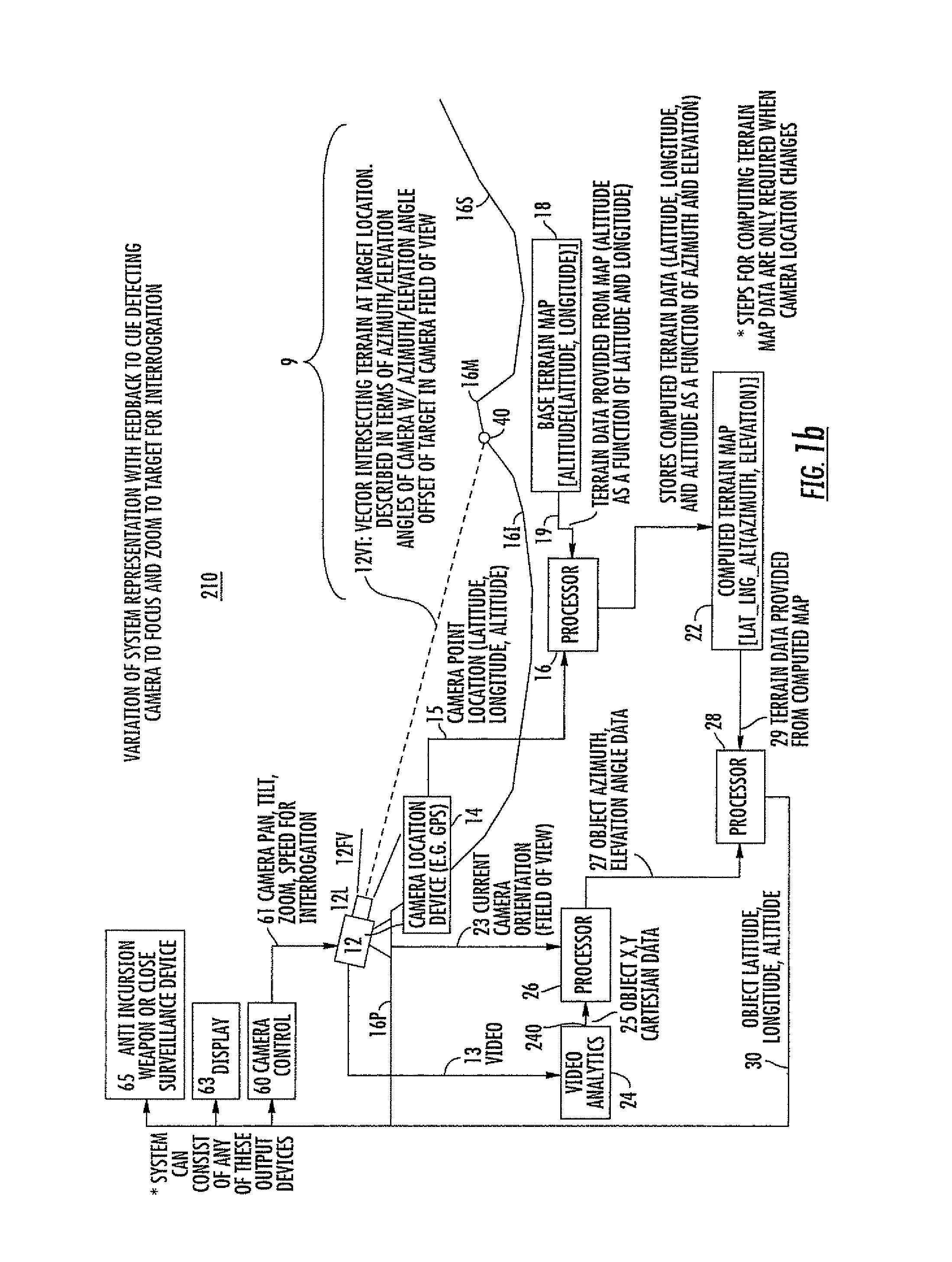
[0018]FIG. 1a represents a system 10 according to an aspect of the invention. The system includes a camera 12 with a lens 12L mounted on a generally planar terrain region 16p. The camera 12 with lens 12 has an instantaneous field of view represented by lines 12fv, which are illustrated as being centered on a field-of-view axis 12vt (but do not necessarily have to be centered). The field of view 12fv encompasses a region of interest 9 which includes a mound 16m, a slope 16s, and an intermediate region 16i. Camera 12 is associated with a cameral location device 14, such as a global positioning system (GPS) receiver, which determines the camera location in terms of latitude, longitude, altitude, and heading, which aids in determining the camera pointing direction in terms of the field of view. The camera 12 location in terms of latitude, longitude, and altitude is transmitted from camera location device 14 by way of a path 15 to a processor illustrated as a block 16. Processor 16 also ...


PUM


Abstract

A method for determining, in three dimensions, the location of a moving ground object observed in a region by a video camera. A terrain map supplies altitude for the latitude and longitude of each terrain point. The terrain information is combined with camera location, field of view, and orientation to produce a computed terrain map relative to the camera. A video analytics step processes the video and locates moving target(s) in two Cartesian coordinates. The coordinates are processed with the camera information to produce target location in terms of azimuth and elevation angle. The computed map information is combined with the angular target location to produce latitude, longitude, and altitude of the target. The target location information is used for further investigation or to attack the target. Also, a method for determining the third dimension of a 2-D radar track to cue a camera or fuse with camera data.

Description

FIELD OF THE INVENTION[0001]This invention relates to the determination of the three-dimensional location of a target in known terrain from sensed two-dimensional information.BACKGROUND OF THE INVENTION[0002]Homeland security has become of more than passing interest. One aspect of security involves surveillance of regions near borders to be protected from invasion, whether the invasion is (a) by hostile troops seeking to enter and attack a region to be protected or'(b) by undocumented or criminal persons, as might occur at the U.S.-Mexican border. One of the problems with such surveillance is that the regions under surveillance may be large, and the manpower available to perform the surveillance may be small. The availability of personnel to counter a detected incursion is a different issue. When the number of eyes available to perform surveillance or to survey is small, there is the possibility, or even the likelihood, that some incursions will not be noticed. Even when a large num...

Claims


Application Information

Patent Timeline
Patent Type & Authority Patents(United States)
IPC IPC(8): G01S13/00G01S13/08G06K9/00G01C21/00
CPCG01C21/005G01S5/16G01S7/046G01S13/723G01S13/867
Inventor LAGONIK, LOUISSMITH, DONNA F.
Owner LOCKHEED MARTIN CORP
Why Eureka
Try Eureka