Ultrasonic ranging sensors

a technology of ultrasonic range and sensors, applied in the field of guidance systems, can solve the problems of time difference between when the signal arrives at the two receivers, and achieve the effects of increasing gain, increasing time-since-transmission, and solving range problems

Inactive Publication Date: 2017-02-16
HARRES DANIEL N
View PDF9 Cites 4 Cited by
  • Summary
  • Abstract
  • Description
  • Claims
  • Application Information

AI Technical Summary

Benefits of technology

[0013]The range problem can be mitigated by providing variable gain in the receivers, by varying the number of pulses from the transmitter, or by varying the threshold. For example, a digital potentiometer can be used in cascade with each of the two receivers, control

Problems solved by technology

However, there is a time difference in whe

Method used


Image

  • Ultrasonic ranging sensors
  • Ultrasonic ranging sensors
  • Ultrasonic ranging sensors

Examples


Embodiment Construction

[0027]According to the embodiment(s) of the present invention, various views are illustrated in FIG. 1-10 and like reference numerals are being used consistently throughout to refer to like and corresponding parts of the invention for all of the various views and figures of the drawing. Also, please note that the first digit(s) of the reference number for a given item or part of the invention should correspond to the Fig. number in which the item or part is first identified.

[0028]One embodiment of the present technology comprising two or more ultrasonic sensing receivers having variable gain teaches a novel apparatus and method for range sensing.

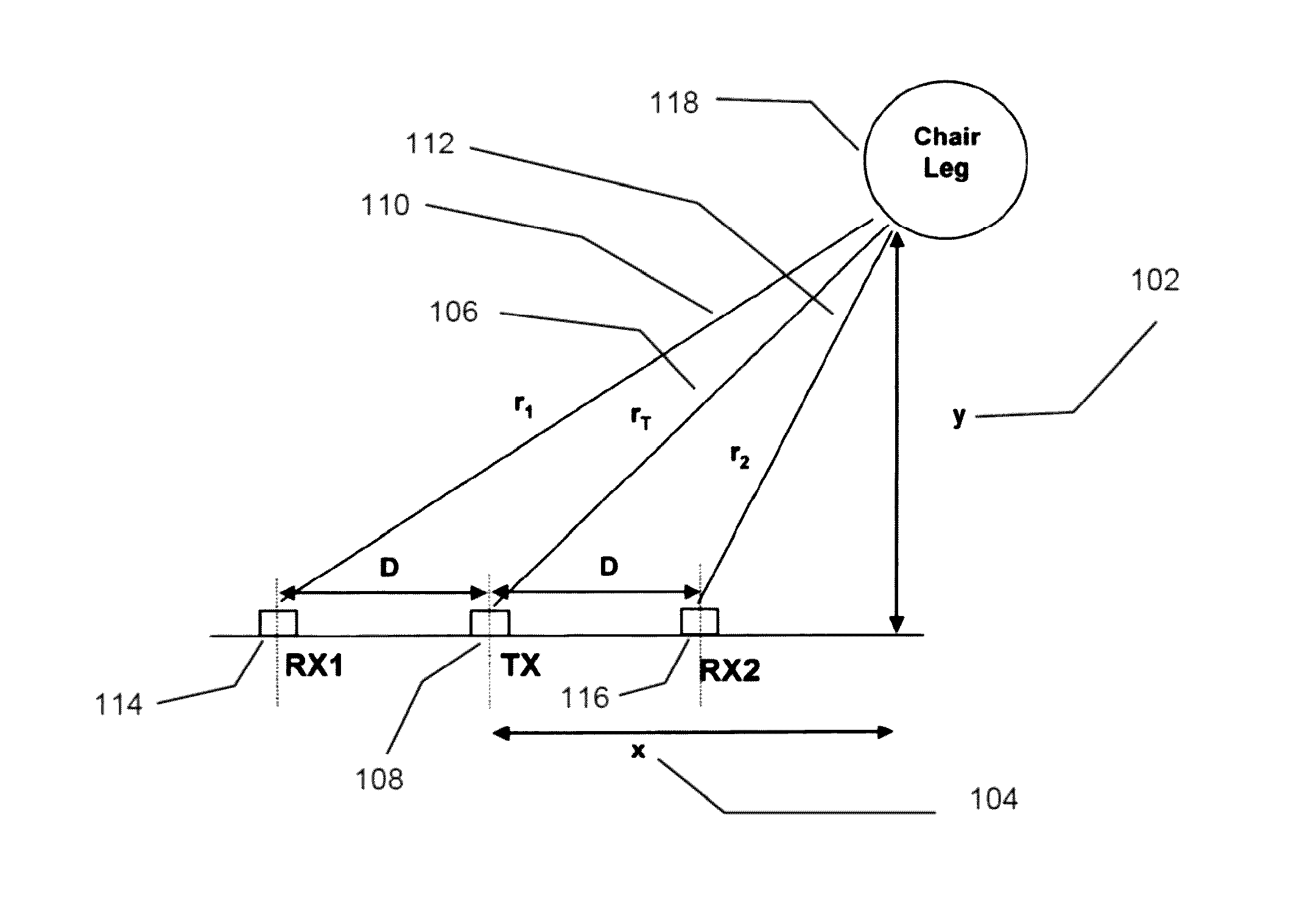
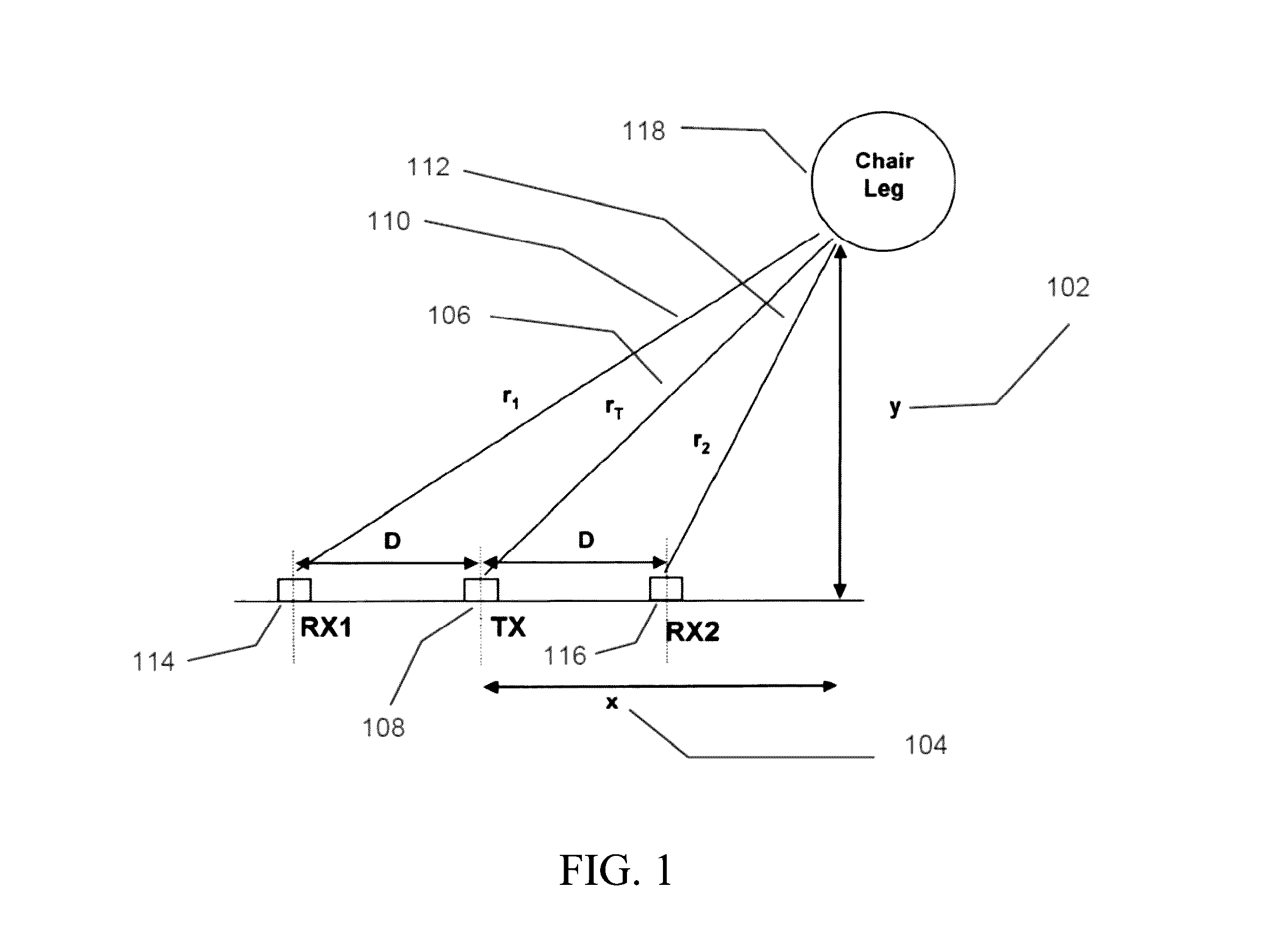
[0029]The details of the invention and various implementations can be better understood by referring to the figures of the drawing. Referring to FIG. 1, the vector y 102, and a vector x 104, along with the vector 106 from transmitter 108 or 110 and 112 from either of the two receivers 114 and 116 to the obstacle 118, form right triangles. By...


PUM


Abstract

An apparatus and method for ultrasonic ranging that allows for the determination of both longitudinal and lateral distances therefore, solving the problem of determining how far to the left or right an object is using such a sensing apparatus by providing variable gain in the receivers, by varying the number of pulses from the transmitter, or by varying the threshold. For example, a digital potentiometer can be used in cascade with each of the two receivers, controlled by the microcontroller, so that the gain can be increased as the time-since-transmission increases. Likewise, the number of pulses can be increased with increasing time-since-transmission, and the threshold can be decreased with increasing time-since-transmission.

Description

BACKGROUND[0001]Field[0002]This technology relates generally to sensors for guidance systems, and, more particularly, to detection of obstacles in the path of a robotic system using signals received by sensors for guidance of the robotic system.[0003]Background Art[0004]Ultrasonic ranging sensors can be used as a means of determining distance to an object. This is particularly useful for automated robotic systems. Typically, a transmitter, capable of producing ultrasonic sound waves, generates an integer number of cycles at the ultrasonic frequency. The time required for the sound to exit the transmitter, strike the obstacle, and reflect to an ultrasonic receiver located near the transmitter can be referred to as time of-flight (TOF) and is a fairly reliable parameter for distance estimation. By dividing the TOF by 2 (to account for the round trip traveled) and multiplying by the speed of sound (˜1100 feet per second for standard temperature and pressure) the distance to the obstacl...

Claims


Application Information

Patent Timeline
IPC IPC(8): G01S15/42G01S7/529G01S15/10
CPCG01S15/42G01S7/529G01S15/10G01S15/003G01S15/46G01S15/876G01S2015/465G01S15/931G01S7/527
Inventor HARRES, DANIEL N.
Owner HARRES DANIEL N
Why Eureka
Try Eureka