
Tractor system and method

Active Publication Date: 2017-03-02
TILMOR LLC
View PDF12 Cites 3 Cited by
  • Summary
  • Abstract
  • Description
  • Claims
  • Application Information

AI Technical Summary

Benefits of technology

The patent is about a system for installing and removing agricultural implements on tractors. The system includes a crane and a modified three-point hitch, which makes it easy to quickly remove or install implements. This system helps to reduce equipment unavailability, which is important for many farming operations.

Problems solved by technology

A major disadvantage of such systems is that the operator of the tractor is unable to see the implement during operation of the tractor without physically looking backwards, which can affect forward looking vision, steering accuracy and operator comfort.
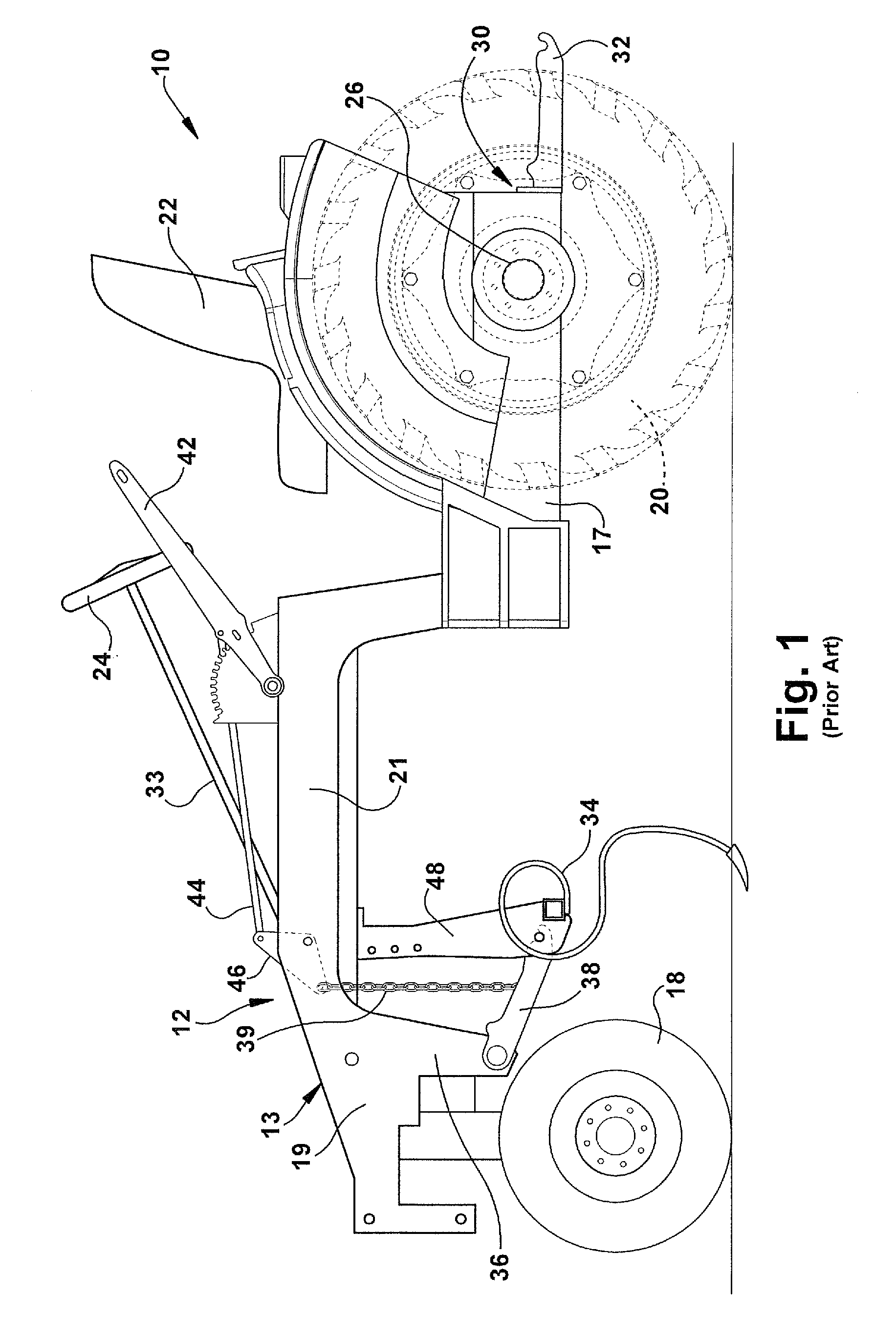
Conventional methods of mounting / installing and detaching / removing implements from tractors featuring attachment of the implement under the tractor frame can be complex and time consuming.
If a single operator is performing the removal / installation of implements the removal of an implement and the subsequent installation of a new implement can result in a significant amount of time that the tractor is unavailable.
However, the carrier system requires additional ground clearance on the part of the tractor due to the height of the wheels or rollers on the carrier and must be located near the implement change-out station.
Further, the wheels or rollers do not function well on rough, uneven, dirt, mud or gravel surfaces that are common in many farm or agricultural operations.
As a result, carrier systems are often undesirable for tractors that are used on such farms or agricultural operations.
This method requires physical exertion and can be risky.
As a result, there are disadvantages associated with conventional implement installation / removal systems for agricultural tractors featuring the ability to accommodate interchangeable implements under the tractor.

Method used


Image

  • Tractor system and method
  • Tractor system and method
  • Tractor system and method

Examples


Embodiment Construction

[0024]The subject matter is described with reference to the drawings, in which like reference numerals are used to refer to like elements throughout the description. In the description, for purposes of explanation, numerous specific details are set forth in order to provide an understanding of the disclosed and claimed subject matter. It will be understood, however, that the disclosed subject matter can be practiced without these specific details.

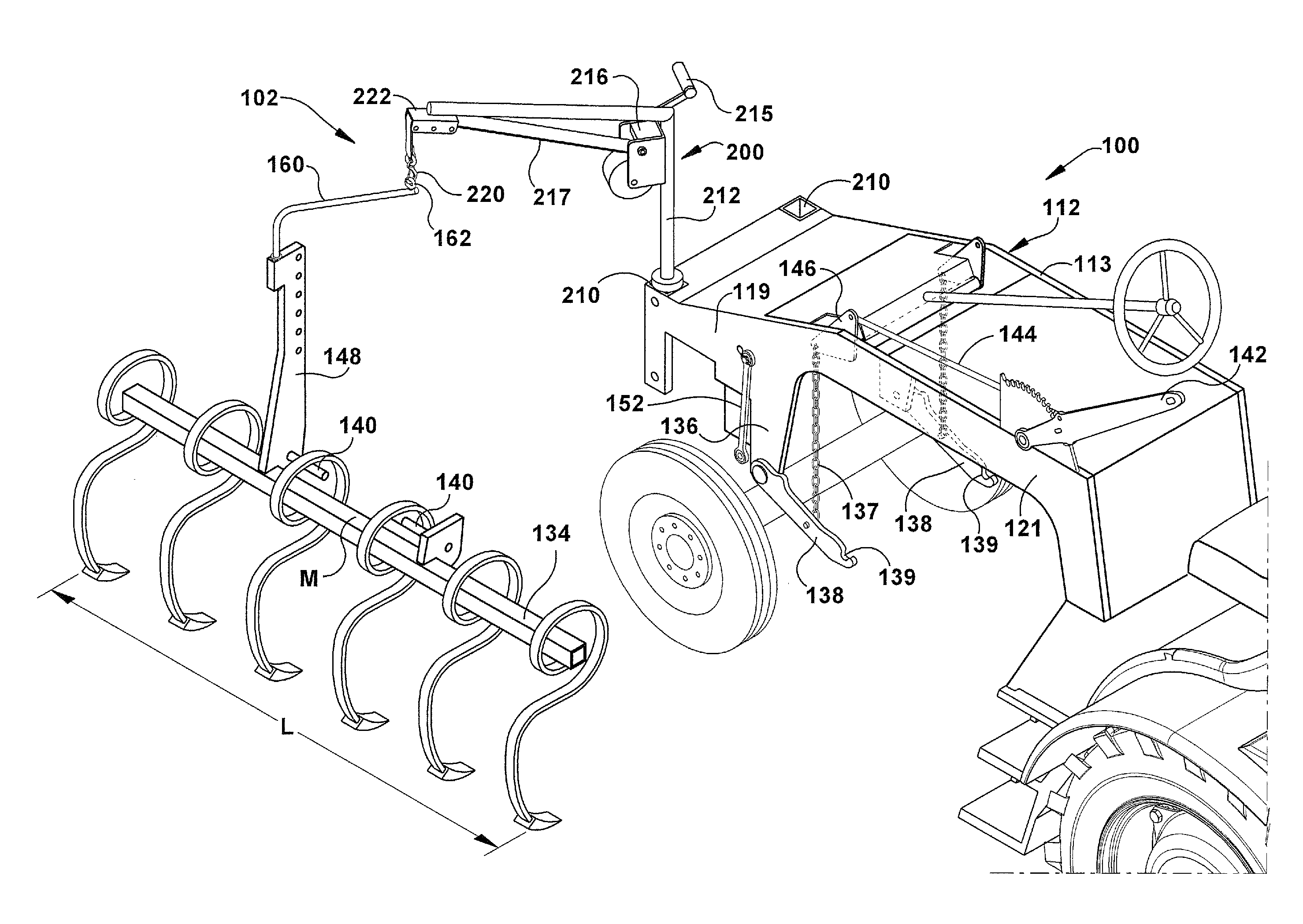
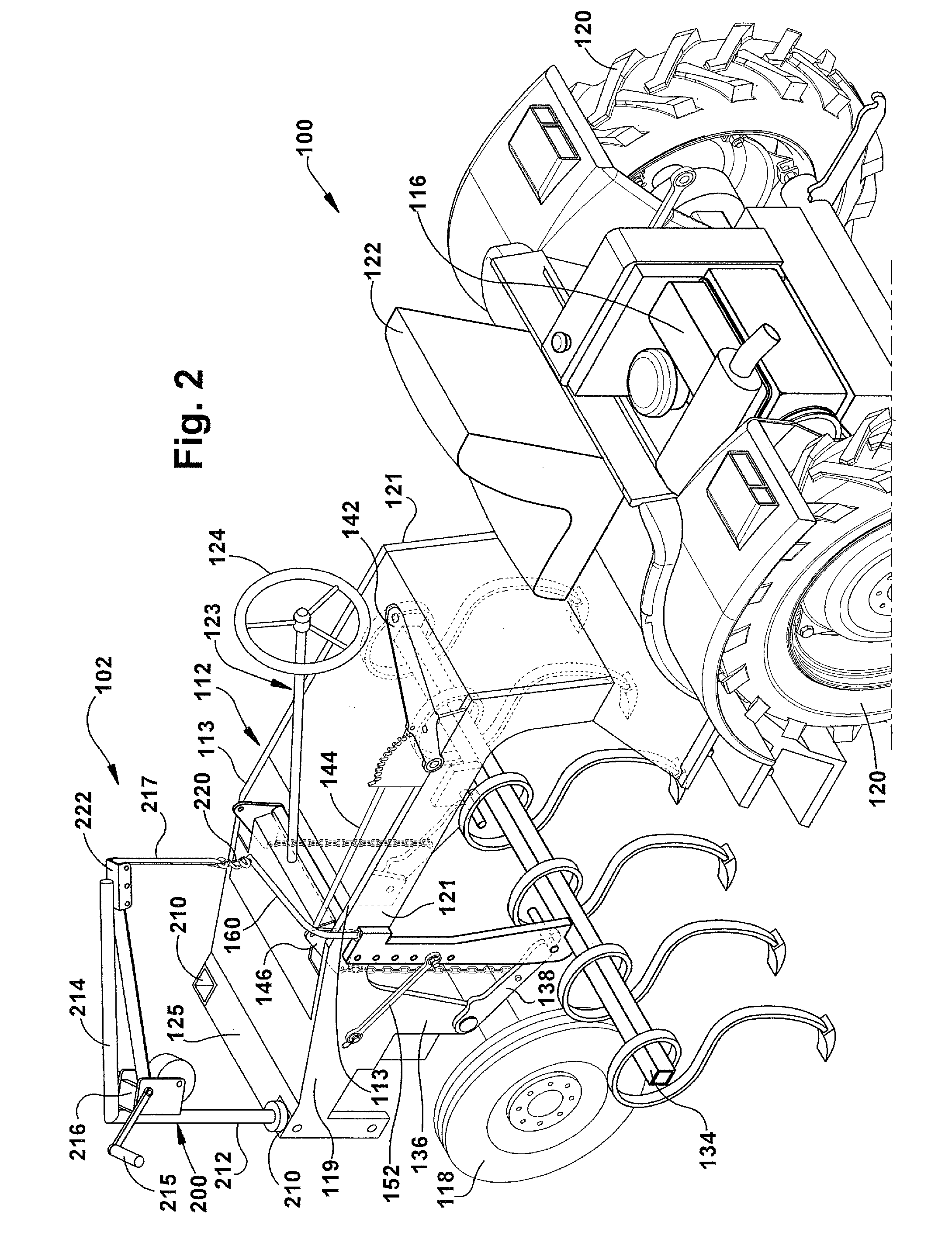
[0025]An implement installation / removal system, according to one aspect of this disclosure, overcomes the disadvantages associated with prior art installation / removal systems for implements that are installed under a tractor frame. Specifically, the implement installation / removal system features the ability to accommodate interchangeable implements by providing a modified three-point hitch system and integral lift mechanism for securing implements under the tractor frame. This implement installation / removal system allows simple and quick re...


PUM


Abstract

An attachment system for removably attaching an implement under a vehicle. The mounting system includes a vehicle frame. The vehicle frame has a pair of spaced apart frame portions. Each of a pair of hitch receiving points is connectable with a respective one of the frame portions. An implement includes support structure extending for a length. A pair of hitch pins is associated with the support structure. The hitch pins are spaced apart in a direction along the length of the support structure. Each hitch pin is for attachment to a respective one of the hitch receiving points. A structural member is associated with the support structure and has a portion adapted to attach to structure outboard of a frame portion. A lift mechanism is connectable with a portion of the vehicle frame. The lift mechanism is attachable with the structural member to move the hitch pins relative to the hitch receiving points.

Description

CROSS-REFERENCE TO RELATED APPLICATIONS[0001]This application claims the benefit of U.S. Provisional Patent Application Ser. No. 62 / 209,945 filed on Aug. 26, 2015.TECHNICAL FIELD[0002]This disclosure generally relates to tractors having interchangeable implements. More particularly, this disclosure relates to an installation / removal system for agricultural tractors that utilize interchangeable implements.BACKGROUND[0003]For many years, the agricultural industry utilized tractors featuring the ability to accommodate interchangeable implements. A tractor with the ability to accommodate interchangeable implements is particularly beneficial to farm or agricultural operations as it allows a single tractor to perform multiple functions. Thus, the need for multiple tractors that are intended for specific particular functions is eliminated, which reduces operational costs.[0004]Typically, interchangeable implements are either attached to the tractor on an attachment hitch system located on ...

Claims


Application Information

Patent Timeline
IPC IPC(8): A01B59/06A01B59/00B62D49/06
CPCA01B59/06B62D49/065A01B3/36A01B59/066A01B59/065A01B59/002
Inventor STEINER, ROY I.STEINER, MARK E.
Owner TILMOR LLC
Learn More