Wearable apparatus for measuring position and action of arm

a technology of arm and arm movement, which is applied in the direction of applications, programs, instruments, etc., can solve the problems of long time for robots to learn complicated motions, robots may take undesired postures, and poor intuition in implementing robots, so as to reduce the learning time of robots, facilitate the movement of both arms, and make the robot quickly and accurately learn the motions

Active Publication Date: 2017-03-02
ELECTRONICS & TELECOMM RES INST
View PDF3 Cites 29 Cited by
  • Summary
  • Abstract
  • Description
  • Claims
  • Application Information

AI Technical Summary

Benefits of technology

[0011]Accordingly, the present invention has been made keeping in mind the above problems occurring in the prior art, and an object of the present invention is to provide a wearable apparatus for measuring position and action of an arm that is worn on a user's arm and enables a robot to intuitionally learn necessary actions by precisely and stably measuring movement of the arm.
[0013]The joints may include: a shoulder joint connected to a side of the main frame; an upper arm member coupled to the shoulder joint; an elbow joint coupled to an end of the upper arm member; a lower arm member coupled to the elbow joint; and a wrist joint coupled to an end of the lower arm member, and at least any one of the shoulder joint, the upper arm member, the elbow joint, the lower arm member, and the wrist joint may have a degree of freedom for straight motion.
[0026]The back joint may include: a back joint frame axially rotatably coupled to the second back frame; and a back joint bracket member coupled to the back joint frame rotatably to the left and right and coupled to the first back support frame rotatably up and down, thereby having a 3-degrees of freedom.
[0030]According to the present invention, an instructor can conveniently move both arms in the apparatus, can precisely instruct a two-arm robot in motions of the instructor's arms, can reduce learning time of the robot, and can make the robot quickly and accurately learn the motions.
[0031]Therefore, according to the present invention, even a non-expert can conveniently and precisely instruct a robot even in complicated motions so that the robot can intuitionally learn the motions.

Problems solved by technology

According to this method, it is possible relatively easily estimate simple motions in the process of designing tracks, but when motions are complicated, an accident such as a collision may be caused due to misjudgment of the user, and additionally the user must learn robot motions by trial and error.
According to this method, however, when a robot having over six degrees of freedom is controlled, the position of an end effector can be moved as it is intended, but the robot may take undesired postures due to a redundant degree of freedom.
Further, since all of motions of the robot are learned only through movement of the front of the robot, intuition of implementing a robot is somewhat poor.
However, even in this case, there is a need for making paths by keeping intermediate points and smoothly connecting them, and it takes long time to make the robot learn complicated motions.
It is preferable that a robot can also recognize and copy motions of the human, but equipment that has been developed thus far has difficulty in precisely recognizing human motions.
Motion capture devices that are usually used for making animations are classified into a type that visually recognizes markers on a body, a type that corrects signals from an inertia sensor using software, and a type that requires wearing a mechanical device, but none of them can measure human motions with high precision.
An exoskeletal wearable device may relatively precisely measure motions in comparison to other devices, but it is complicated, and especially the shoulders of the human have a complicated structure of 7-degree of freedom, but at present it is difficult to design a mechanism for measuring even only three-directional rotation. FIG. 1 shows a 3-degree of freedom link assembly rotating about the rotational center of a shoulder and FIG. 2 shows a link mechanism with an additional degree of freedom for the back in the 3-degree of freedom link assembly.
These assemblies are designed such that their shoulder centers are supposed to be aligned to the shoulder center of a person, but the shoulder makes complicated motions, so it is difficult to keep the rotational centers of the assemblies aligned to the rotational center of the shoulder, and accordingly, it may be inconvenient to move the shoulder due to corresponding resistance.
Further, it is difficult to design a device that precisely measures forearm pronation / supination.

Method used


Image

  • Wearable apparatus for measuring position and action of arm
  • Wearable apparatus for measuring position and action of arm
  • Wearable apparatus for measuring position and action of arm

Examples


Embodiment Construction

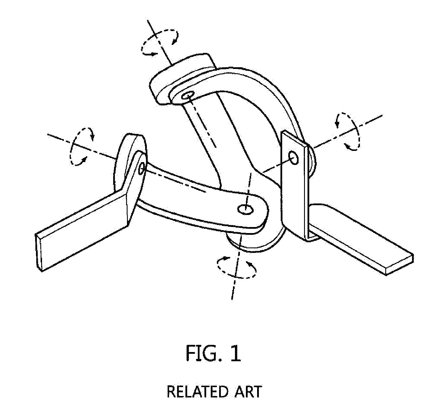
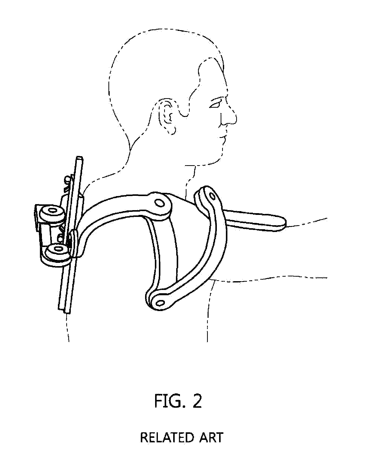
[0042]The present invention will be described in detail below with reference to the accompanying drawings. Repeated descriptions and descriptions of known functions and configurations which have been deemed to make the gist of the present invention unnecessarily obscure will be omitted below. The embodiments of the present invention are intended to fully describe the present invention to a person having ordinary knowledge in the art to which the present invention pertains. Accordingly, the shapes, sizes, etc. of components in the drawings may be exaggerated to make the description clearer.

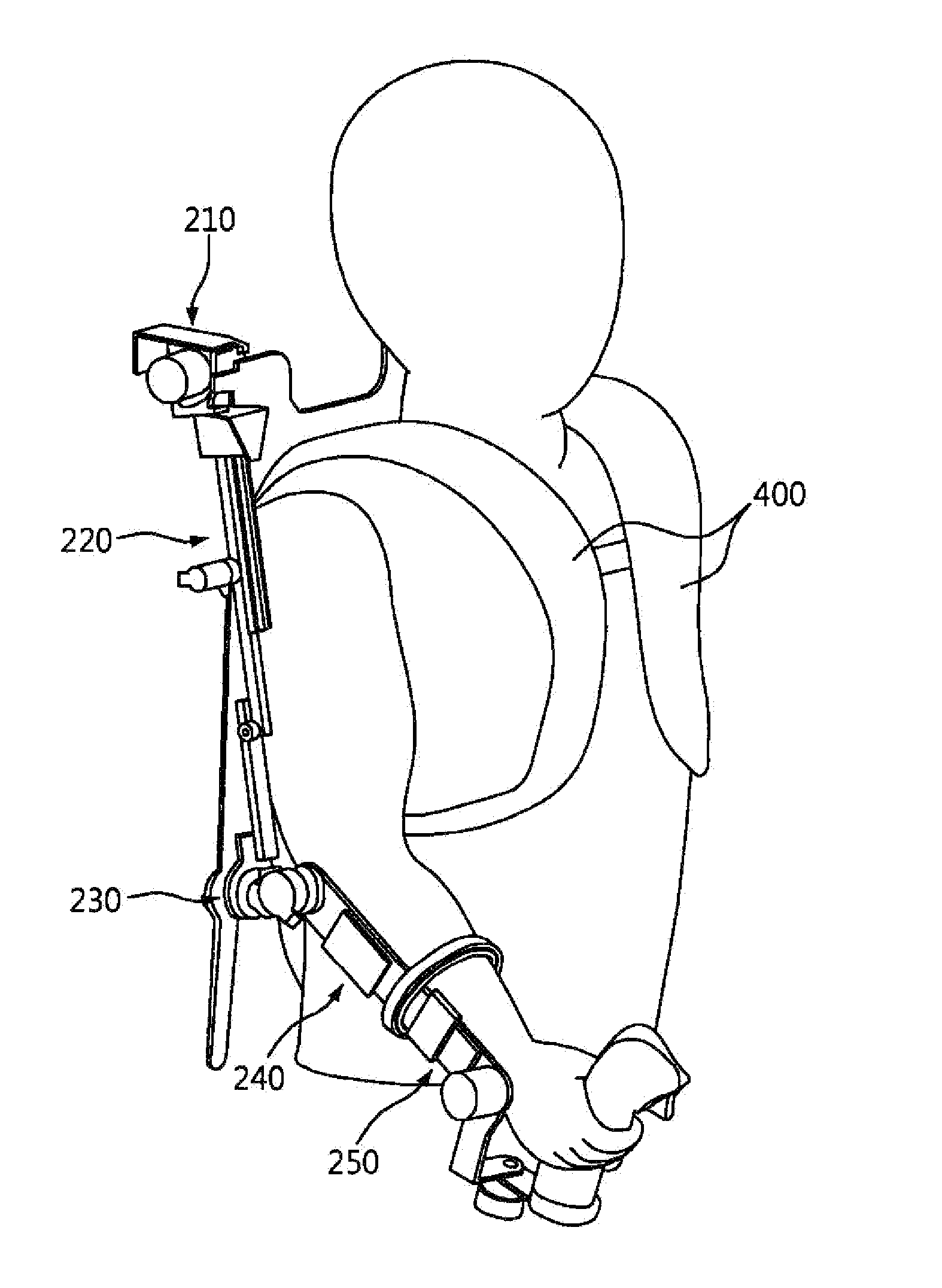
[0043]FIG. 3 is a perspective view showing an embodiment of a wearable apparatus for measuring position and action of an arm according to an embodiment of the present invention and FIG. 4 is a schematic view showing an embodiment of a wearable apparatus for measuring position and action of an arm according to an embodiment of the present invention.

[0044]A wearable apparatus for measuring position a...


PUM


Abstract

A wearable apparatus for measuring position and action of an arm includes: a main frame worn on an upper body of a user; and an arm motion-measuring unit connected to a side of the main frame, having a plurality of joints, and worn on an arm of a user, in which at least any one of the joints of the arm motion-measuring unit has a straight-motional degree of freedom. Accordingly, an instructor can conveniently move both arms in the apparatus, can precisely instruct a two-arm robot in motions of the instructor's arms, can reduce learning time of the robot, and can make the robot quickly and accurately learn the motions.

Description

CROSS REFERENCE TO RELATED APPLICATION(S)[0001]This application claims the benefit of Korean Patent Application No. 10-2015-0119464, filed on Aug. 25, 2015, which is hereby incorporated by reference in its entirety into this application.BACKGROUND OF THE INVENTION[0002]1. Technical Field[0003]The present invention relates to a wearable apparatus for measuring position and action of an arm. More particularly, the present invention relates to a wearable apparatus that is worn on a user's arm for measuring a position and action of the arm and enables a robot to intuitionally learn necessary actions by precisely and stably measuring movement of the arm.[0004]2. Description of the Related Art[0005]As robots are used in various fields, the robots increasingly replace people for work. Various types of robots are used to repeatedly perform relatively simple and easy work or to work under severe environments that are difficult for people to work in. Further, robots mimicking humans are now u...

Claims


Application Information

Patent Timeline
Patent Type & Authority Applications(United States)
IPC IPC(8): A61B5/11
CPCY10S901/15A61B5/1121A61B5/6824B25J3/04B25J9/0006B25J9/1689B25J13/025B25J13/085G05B19/427G05B2219/40305
Inventor LEE, HOO-MANKIM, JOONG-BAEBANG, YOUNG-BONGLEE, CHANG-HYUKCHOI, JI-WON
Owner ELECTRONICS & TELECOMM RES INST
Why Eureka
Try Eureka