Variable focal length lens system

a lens system and variable technology, applied in the field of variable focal length lens system, can solve the problems of inability inability to achieve sufficient miniaturization, failure to achieve predetermined optical performance, etc., and achieve the effect of enhancing the magnifying power

Inactive Publication Date: 2010-12-07
SONY CORP
View PDF11 Cites 17 Cited by
  • Summary
  • Abstract
  • Description
  • Claims
  • Application Information

AI Technical Summary

Benefits of technology

[0017]Generally, in a zoom lens, the power variation ratio can be increased without increasing the optical overall length by increasing the refracting power of the lens groups.
[0020]On the other hand, where the number of movable lens groups is increased, the degree of freedom in selection of the zoom locus of each lens group increases, and consequently, variation of various aberrations which appear when the focal length varies can be corrected favorably. Therefore, even where the power variation ratio is high, miniaturization can be achieved.
[0024]Therefore, it is desirable to provide a variable focal length lens system which solves the problems described above and can achieve enhancement of the magnifying power and miniaturization without complicating a lens barrel structure.
[0030]where the variable focal length lens system is configured so as to satisfy the conditional expressions (2) and (3), the lens diameter of the first lens group does not become excessively great and the amount of movement of the sixth lens group necessary when the lens position state varies increases.
[0032]where the variable focal length lens system is configured so as to satisfy the conditional expressions (4) and (5), the refracting power of the first and second lens groups does not become excessively high and the lens total length in the telephoto end state becomes appropriate.
[0034]where the variable focal length lens system is configured so as to satisfy the conditional expression (6), the lens diameter of the sixth lens group does not become excessively great and the diameter of an on-axis light flux and an off-axis light flux does not become excessively small.

Problems solved by technology

However, such a zoom lens of a four-group configuration of positive, negative, positive, and positive powers as disclosed in Patent Document 1 has a problem in that, if it is tried to assure a high power variation ratio exceeding 20 times, then it becomes difficult to achieve sufficient miniaturization as described below.
However, if the refracting power of the lens groups is increased, then it becomes impossible to correct variation of various aberrations which appear when the focal length varies, resulting in failure to achieve a predetermined optical performance.
Accordingly, where a predetermined optical performance is achieved, miniaturization cannot be achieved and increase in scale cannot be avoided.
Therefore, it is necessary to set the power variation action and the aberration correction action of the first and second lens groups to high levels, and this makes it difficult to assure miniaturization and a high power variation ratio.

Method used


Image

  • Variable focal length lens system
  • Variable focal length lens system
  • Variable focal length lens system

Examples


first embodiment

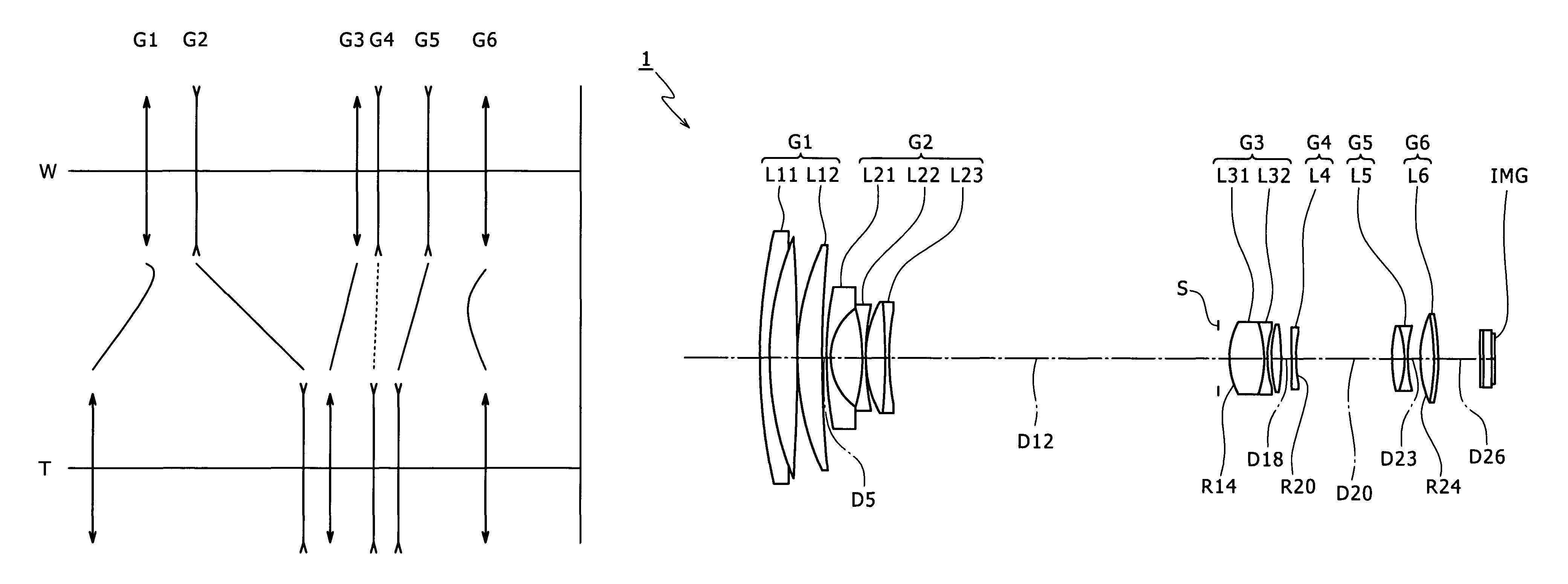
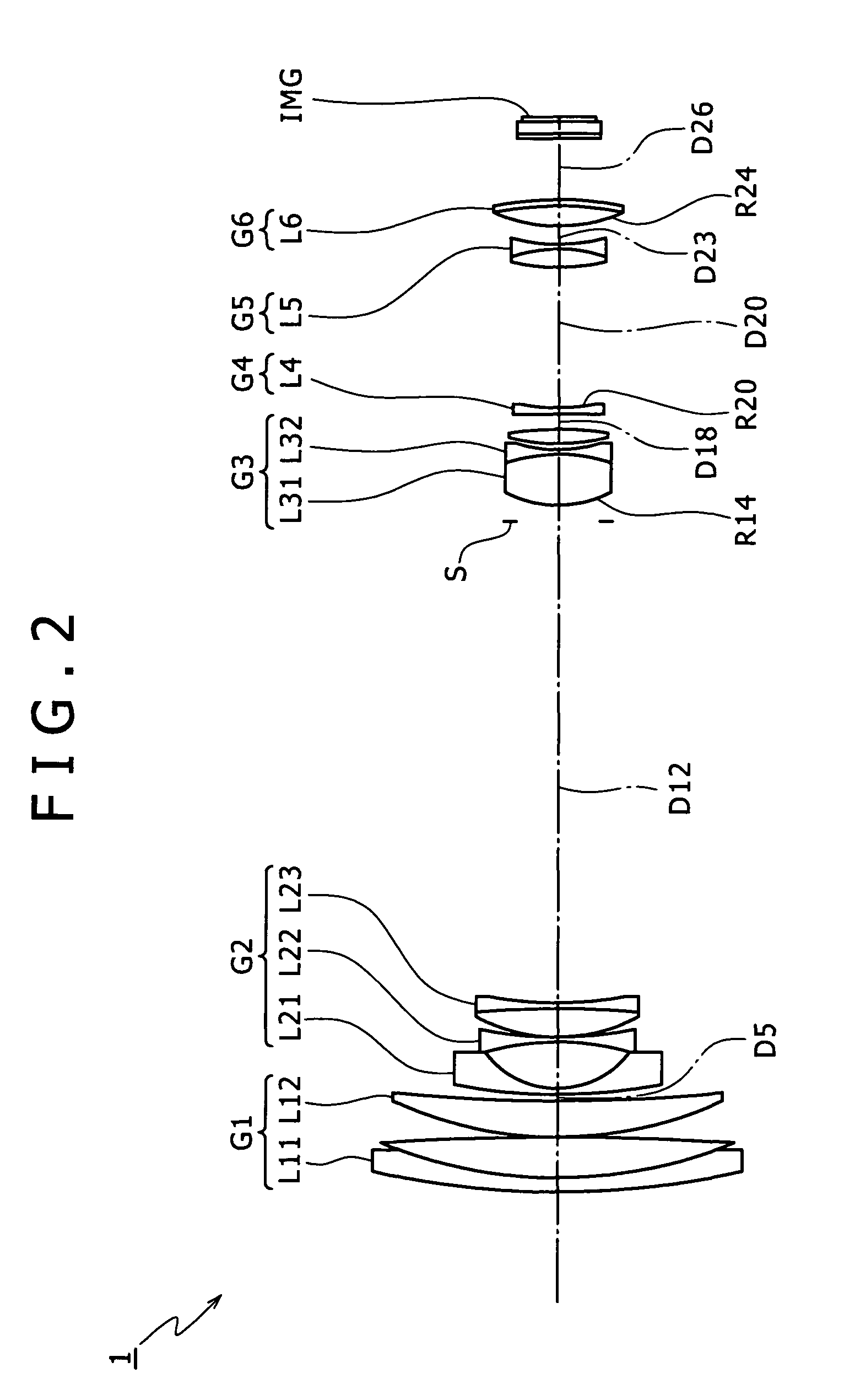
[0172]FIG. 2 shows a lens configuration of a variable focal length lens system 1 according to the present invention. Referring to FIG. 2, the variable focal length lens system 1 includes 15 lenses.

[0173]The first lens group G1 includes a cemented lens L11 of a negative lens of a meniscus shape having a convex face directed to the object side and a positive lens having a convex face directed to the object side, and a positive lens L12 having a convex face directed to the object side.

[0174]The second lens group G2 includes a negative lens L21 of a meniscus shape having a concave face directed to the image side, a negative lens L22 of a biconcave shape, and a cemented lens L23 of a positive lens of a biconvex shape and a negative lens of a biconcave shape.

[0175]The third lens group G3 includes a cemented lens L31 of a positive lens of a biconvex shape and a negative lens of a biconcave shape, and a positive lens L32 of a biconvex shape.

[0176]The fourth lens group G4 includes a negative...

second embodiment

[0194]FIG. 7 shows a lens configuration of a variable focal length lens system 2 according to the present invention. Referring to FIG. 7, the variable focal length lens system 2 shown includes 15 lenses.

[0195]The first lens group G1 includes a cemented lens L11 of a negative lens of a meniscus shape having a convex face directed to the object side and a positive lens having a convex face directed to the object side, and a positive lens L12 having a convex face directed to the object side.

[0196]The second lens group G2 includes a negative lens L21 of a meniscus shape having a concave face directed to the image side, a negative lens L22 of a biconcave shape, and a cemented lens L23 of a positive lens of a biconvex shape and a negative lens of a biconcave shape.

[0197]The third lens group G3 includes a cemented lens L31 of a positive lens of a biconvex shape and a negative lens of a biconcave shape, and a positive lens L32 of a biconvex shape.

[0198]The fourth lens group G4 includes a ne...

third embodiment

[0215]FIG. 12 shows a lens configuration of a variable focal length lens system 3 according to the present invention. Referring to FIG. 12, the variable focal length lens system 3 shown includes 12 lenses.

[0216]The first lens group G1 includes a cemented lens L11 of a negative lens of a meniscus shape having a convex face directed to the object side and a positive lens having a convex face directed to the object side, and a positive lens L12 having a convex face directed to the object side.

[0217]The second lens group G2 includes a negative lens L21 of a meniscus shape having a concave face directed to the image side and a cemented lens L22 of a negative lens of a biconcave shape and a positive lens of a meniscus shape having a convex face directed to the object side.

[0218]The third lens group G3 includes a cemented lens L3 of a positive lens of a biconvex shape and a negative lens of a meniscus shape having a concave face directed to the object side.

[0219]The fourth lens group G4 in...


PUM


Abstract

A variable focal length lens system includes: a first lens group having a positive refracting power; a second lens group having a negative refracting power; a third lens group having a positive refracting power; a fourth lens group having a negative refracting power; a fifth lens group having a negative refracting power; and a sixth lens group having a positive refracting power; the first to sixth lens groups being disposed in order from an object side.

Description

BACKGROUND OF THE INVENTION[0001]1. Field of the Invention[0002]This invention relates to a variable focal length lens system, and more particularly to a technical field of a variable focal length lens system which is used for video cameras, digital still cameras and so forth and has a zoom ratio higher than 20 times.[0003]2. Description of the Related Art[0004]In related art, a method is known wherein an image pickup device which uses a photoelectric conversion element such as a CCD (Charge Coupled Device) element or a CMOS (Complementary Metal Oxide Semiconductor) element as recording means for a camera is used such that the amount of light of an image of an image pickup object formed on a face of the image pickup element is converted into and recorded as an electric output.[0005]Further, together with the progress of a microprocessing technique in recent years, enhancement of the operation speed of a central processing unit and the integration of a storage medium has been achieve...

Claims


Application Information

Patent Timeline
Patent Type & Authority Patents(United States)
IPC IPC(8): G02B15/14
CPCG02B15/173G02B15/1461
Inventor OHTAKE, MOTOYUKI
Owner SONY CORP
Why Eureka
Try Eureka