

Multipurpose load lifting work platform or/and composite bridge structure
a multi-purpose, work platform technology, applied in the direction of bridges, building scaffolds, lifting devices, etc., can solve the problems of limited use range, poor horizontal stability of load, and each equipment consumes a considerable amount of energy during operation
- Summary
- Abstract
- Description
- Claims
- Application Information
AI Technical Summary
Benefits of technology
Problems solved by technology
Method used
Image

Examples
Embodiment Construction
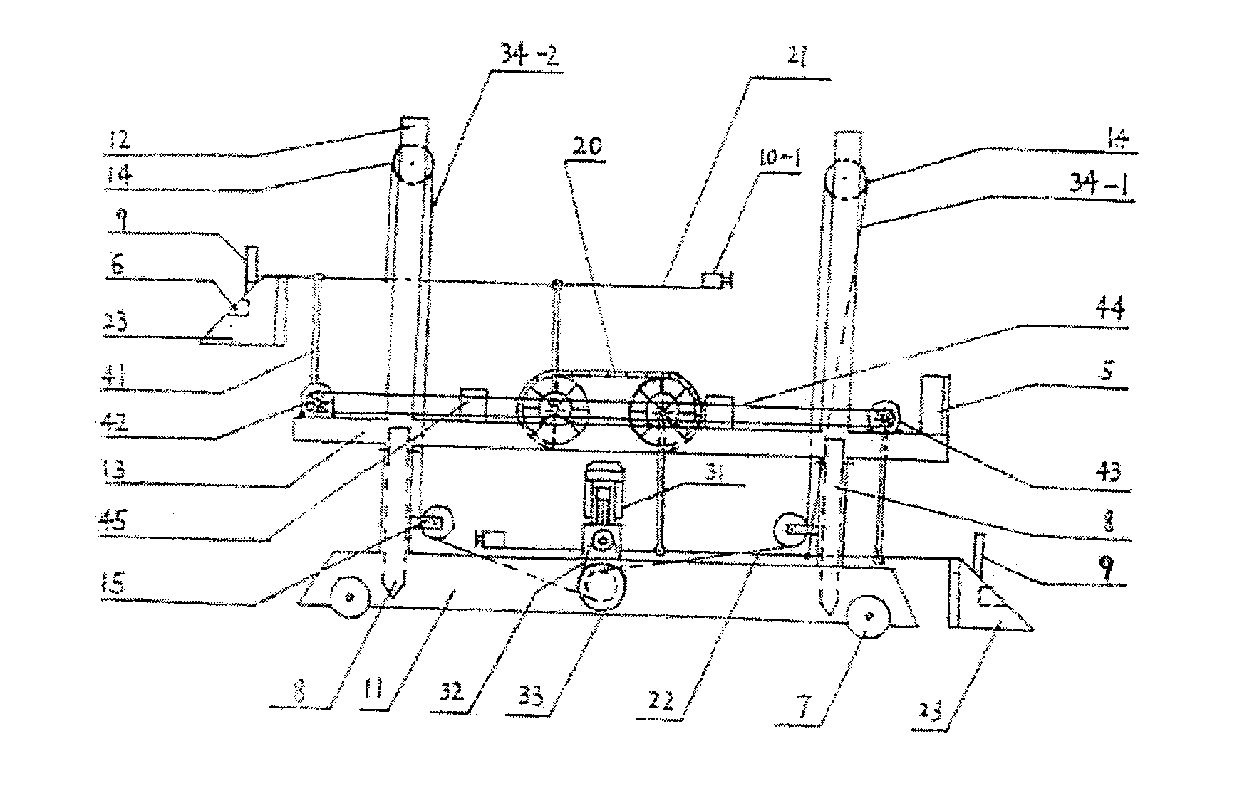
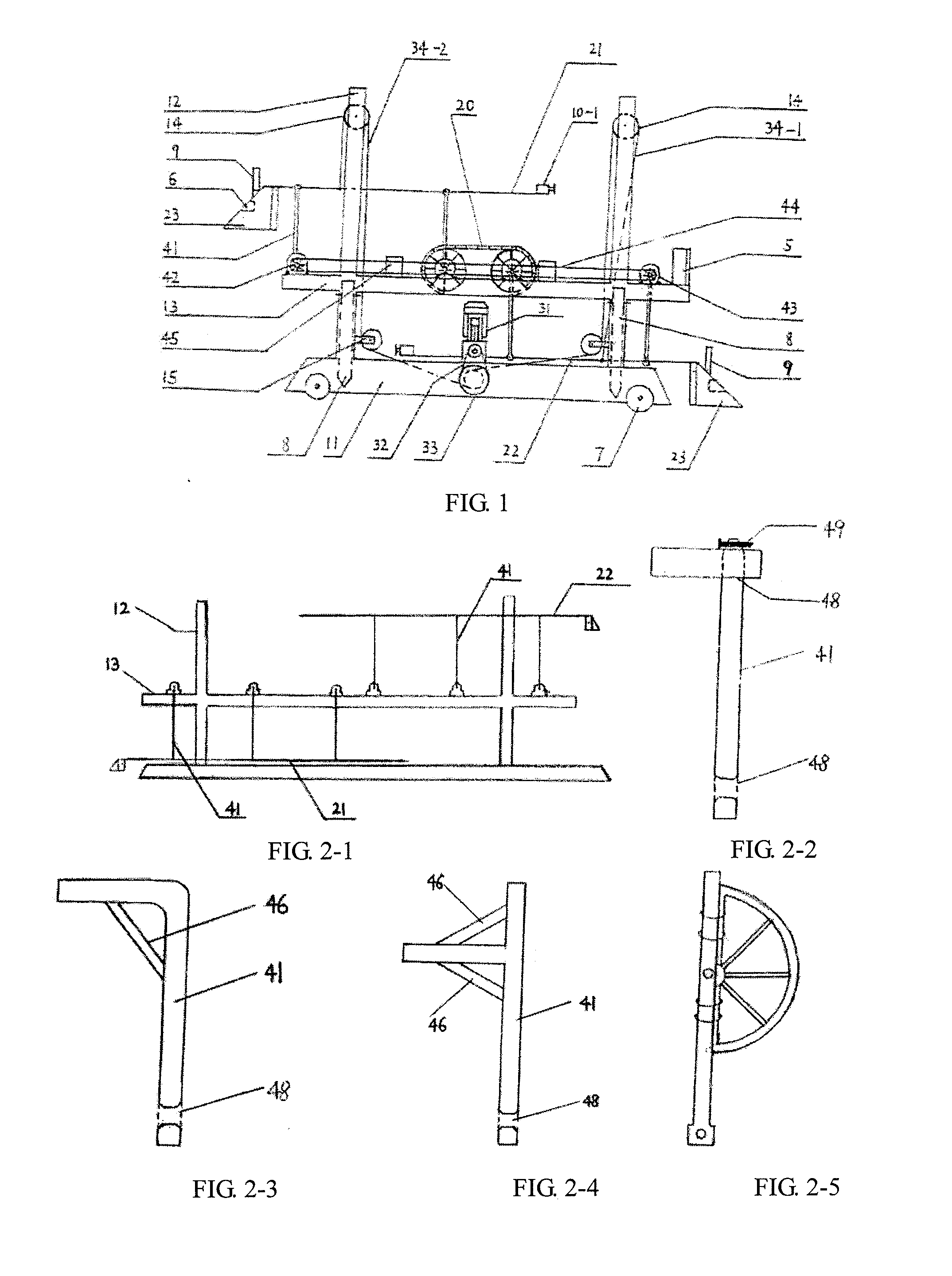
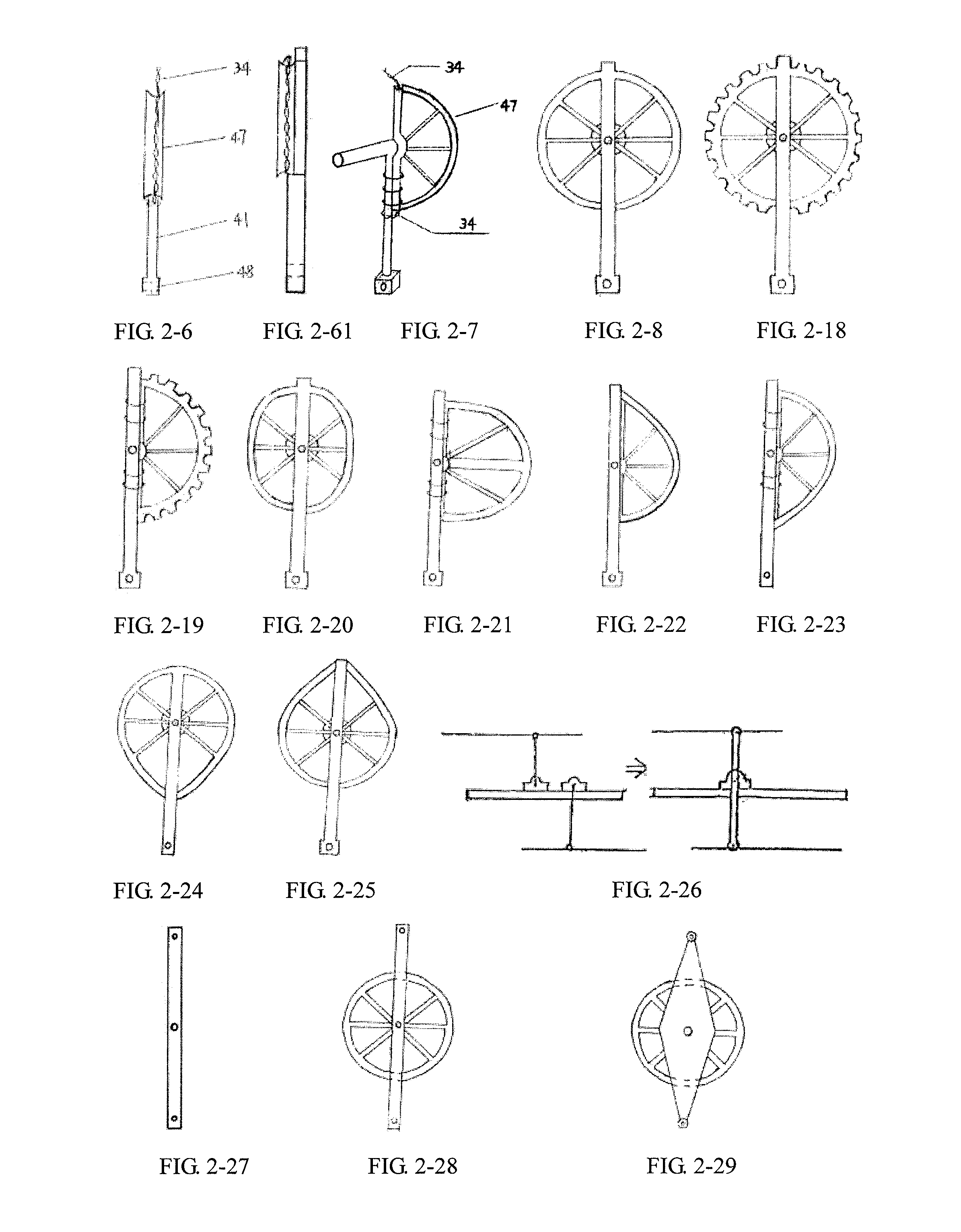
[0049]Hereinafter, the invention will be further described in combination with drawings and examples. The framework is selected as a four-column type framework with pulleys at its top, and the load is exampled as vehicle. Due to different types of the pole-shaped structures selected, the driving mode of the equipment is different, which is embodied in the different position for connection of the steel wire rope or chain 34. Now the description will be provided according to two types:
[0050]Type 1: when the right-angle pole-shaped structures shown in FIGS. 2-1, 2-2 and 2-3 are selected, the steel wire rope or chain 34 are fixed on the work platform, as shown in FIGS. 5, and 34 can be selected as steel wire rope or chain, or be selected as cord or conveyer belt. Hereinafter, in order to simplify the description, 34 will be exampled as the steel wire rope throughout the description. When a vehicle is parked on the work platform 22 and the work platform 22 is moved to the upper level, th...
PUM
 Abstract
Description
Claims
Application Information