Novel fuel production plant and seawater desalination system for use therein

a technology of desalination system and fuel production plant, which is applied in the direction of multiple-effect evaporation, machine/engine, separation process, etc., can solve the problems of large amount of excess heat, large amount of cooling water required by steam turbines, and merit of using seawater as cooling water, so as to reduce maintenance costs and reduce the remaining salinity of produced water

a technology of desalination system and fuel production plant, which is applied in the direction of multiple-effect evaporation, machine/engine, separation process, etc., can solve the problems of large amount of excess heat, large amount of cooling water required by steam turbines, and merit of using seawater as cooling water, so as to reduce maintenance costs and reduce the remaining salinity of produced water

US20070039324A1Inactive Publication Date: 2007-02-22HITACHI LTD

Image

  • Novel fuel production plant and seawater desalination system for use therein
  • Novel fuel production plant and seawater desalination system for use therein

Examples


Embodiment Construction

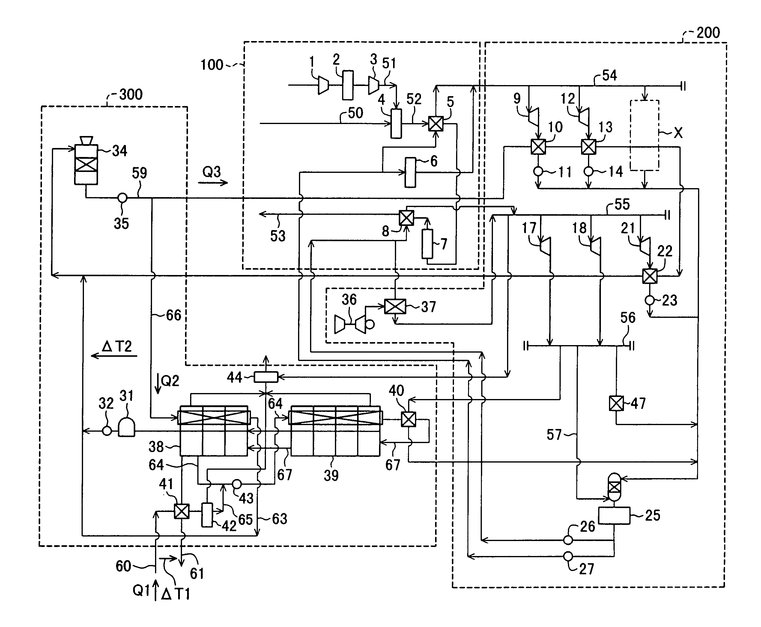
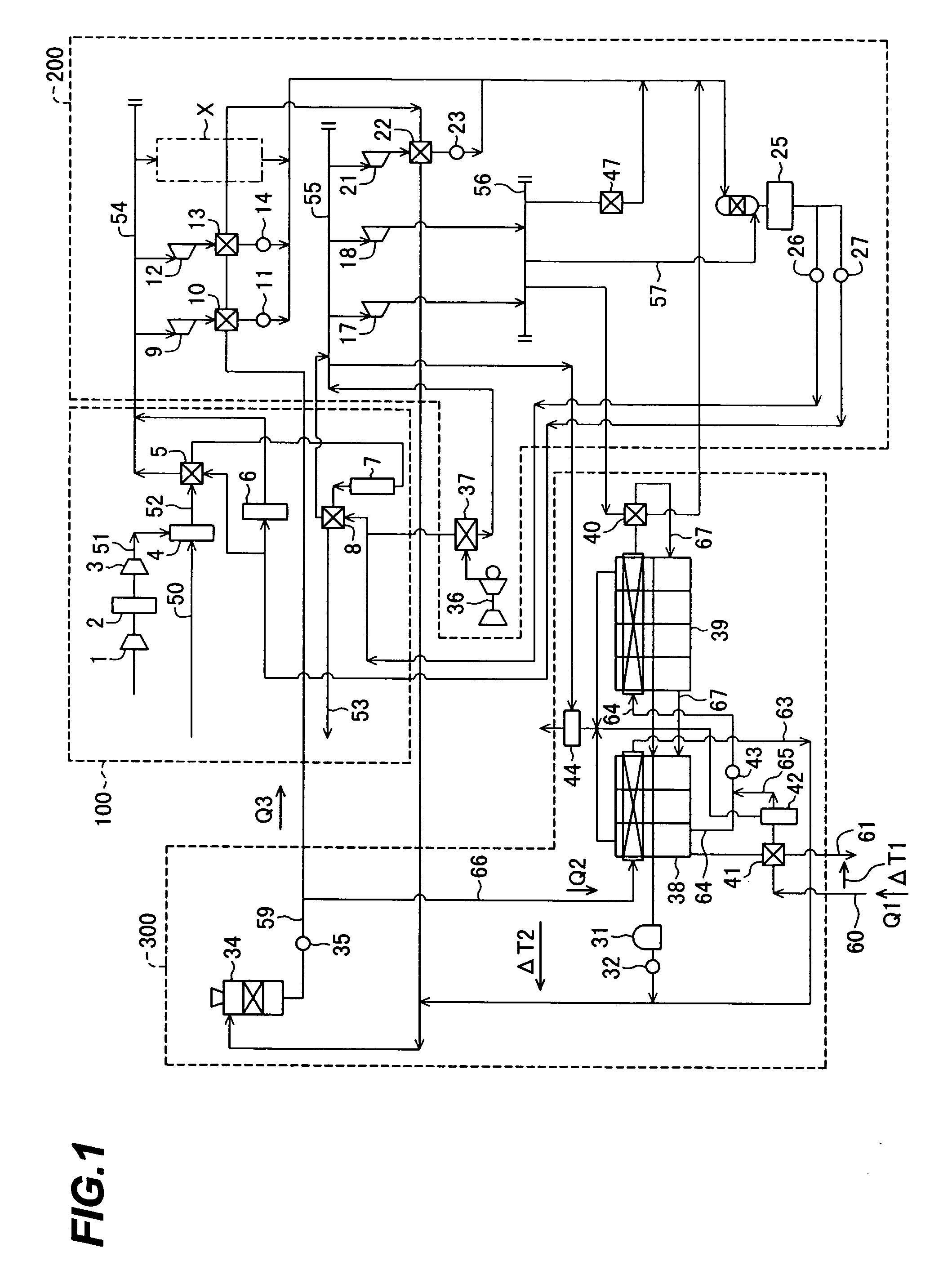
[0012] The construction of a novel fuel production plant according to one embodiment of the present invention will be described below with reference to FIG. 1.

[0013]FIG. 1 is a diagram showing the construction of the novel fuel production plant according to one embodiment of the present invention.

[0014] The novel fuel production plant of this embodiment comprises a novel fuel producing section 100, an exhaust heat utilizing section 200, and a cooling water supply section 300. The novel fuel producing section 100 produces new fuel from a feedstock and generates steam by utilizing exhaust heat. In the exhaust heat utilizing section 200, steam turbines are driven using the steam generated by the novel fuel producing section 100, to thereby drive rotary machines, etc. The cooling water supply section 300 supplies cooling water used in condensers for the steam turbines in the exhaust heat utilizing section 200.

[0015] The novel fuel producing section 100 comprises an air compressor 1, ...


PUM

PropertyMeasurementUnit
temperatureaaaaaaaaaa
temperaturesaaaaaaaaaa
temperatureaaaaaaaaaa

Abstract

A novel fuel producing section produces synthesized gas from a feedstock and synthesizes novel fuel from the synthesized gas thus produced, and has exhaust heat recovery boilers for generating steam by recovering excess heat generated from the synthesizing processes. An exhaust heat utilizing section includes steam turbines driven with the steam generated from the exhaust heat recovery boilers. An open circulation cooling water supply section supplies cooling water for a plant, including water for cooling exhausts of the steam turbines, and includes a seawater desalination system for desalinating seawater by the evaporation method and supplying desalinated water to replenish the cooling water. The cooling water supplied from the open circulation cooling water supply section is used in condensing of the desalinated water produced by the seawater desalination system.

Description

TECHNICAL FIELD [0001] The present invention relates to a novel fuel production plant for producing novel fuel, and to a seawater desalination system for use in the plant. BACKGROUND ART [0002] Recently, attention has been focused on plants for producing novel fuel, such as Gas-To-Liquid (GTL) and dimethylether (DME). As a novel fuel production plant, one known example for producing dimethylether by using natural gas as a feedstock is disclosed in, e.g., JP,A 10-195008. DISCLOSURE OF THE INVENTION [0003] In plants for producing novel fuel, such as GTL and DME, (hereinafter referred to as “novel fuel production plants” or simply as “plants”), for example, a partial oxidation method or an auto-thermal reforming method using hydrocarbons, etc. as a feedstock is employed to produce synthesized gas necessary for synthesizing fuel. In those synthesized gas producing methods, the temperature of the synthesized gas at an outlet of a reaction / reforming furnace is very high (1200-1500° C.). O...

Claims


Application Information

Patent Timeline
22 Feb 2007
Publication
US20070039324A1
IPC
F01K23/06; C02F1/16
CPC
C02F2103/08; C02F1/16; B01D1/26; B01D3/065; C02F1/06; Y02P70/10; Y02A20/124; Y02A20/131
Inventors
INUI, TAIJI; KAWAGUCHI, TSUNEHISA