Pliers

a technology of pliers and pliers, which is applied in the field of pliers, can solve the problems of inability to rotate, inability to do rotational movement, and inability to do drilling,

Active Publication Date: 2009-02-19
WEZAG - WERKZEUGFAB
View PDF30 Cites 17 Cited by
  • Summary
  • Abstract
  • Description
  • Claims
  • Application Information

AI Technical Summary

Benefits of technology

[0014]According to the invention, the cutting element might have a degree of freedom in circumferential direction with respect to the seat and the cable located in the seat. During the step of providing the circumferential carving the pliers might be held without any rotation of the pliers itself. However, the cutting element is moved in circumferential direction or rotated around the longitudinal axis of the seat resulting in a simplified use that is in particular also possible in small spaces.
[0016]According to the invention, it is possible to partially or completely avoid the aforementioned frictional forces or slipping movement between the seat, supporting surfaces and the cable. This is due to the fact that it is possible that the seat is not rotated throughout the cutting or carving process. Furthermore, it is possible that during the rotation of the cutting element according to the invention the force applied by the cutting element also rotates leading to a rotating counterforce applied by the seat. The drilling deflection of the cable is avoided also without any slipping movement between the supporting surfaces and the cable. Furthermore, it might be possible that frictional forces directed in circumferential direction during the rotation of the cutting element are counteracted by frictional forces at the supporting surfaces of the seat. The counterforces are located with a small axial distance but on the opposite side of the cable so that there is no or only a small drilling of the cable.
[0021]For a different embodiment the cutting element might be pressed with a defined radial force in radial direction versus the cable. The radial force might not result in any carving or cutting or might result in a carving or cutting of the cable with a depth smaller than the final depth. During the subsequent relative movement of the cutting element in circumferential direction the cutting element is still pressed in radial direction against the outer circumference of the cable continuing the carving or cutting in circumferential direction and / or increasing the depth of the cutting or carving. For such embodiment, it is possible that the depth of the carving or cutting is increased with a relative rotation between the seat and the cable and the cutting element of more than 360° wherein an increase of the angle of rotation is related with an increase of the depth of the carving or cutting.
[0025]In order to avoid an undesired depth of the cutting or carving, another embodiment of the invention suggests providing a stop element limiting the minimal radial distance of the cutting element from the seat.
[0031]In another aspect of the invention, an ejection unit is provided for ejecting, pushing or sliding the cable or cut or carved parts or layers of the cable at the end of the cutting process out of the pliers. By means of the ejecting unit an awkward removal of cut residues out of the seat might be avoided.

Problems solved by technology

Such rotational movement is awkward to do for the user and is not possible in small spaces.
Such drilling forces are undesired.

Method used


Image

  • Pliers
  • Pliers
  • Pliers

Examples


Embodiment Construction

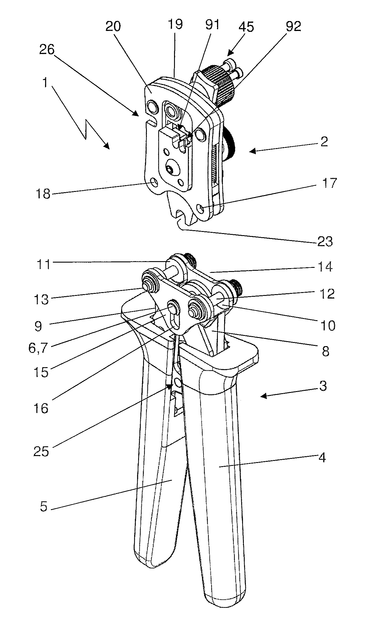
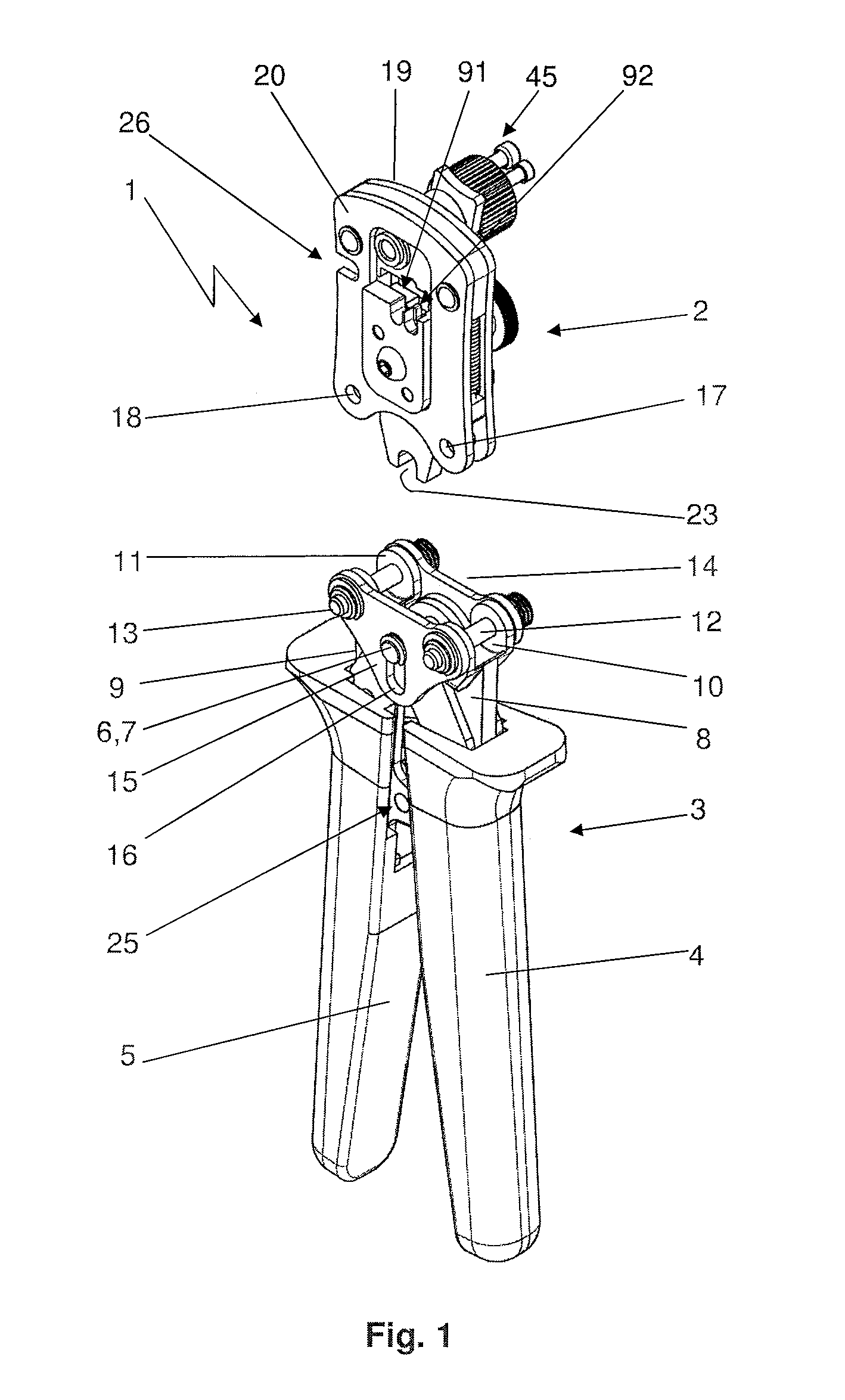
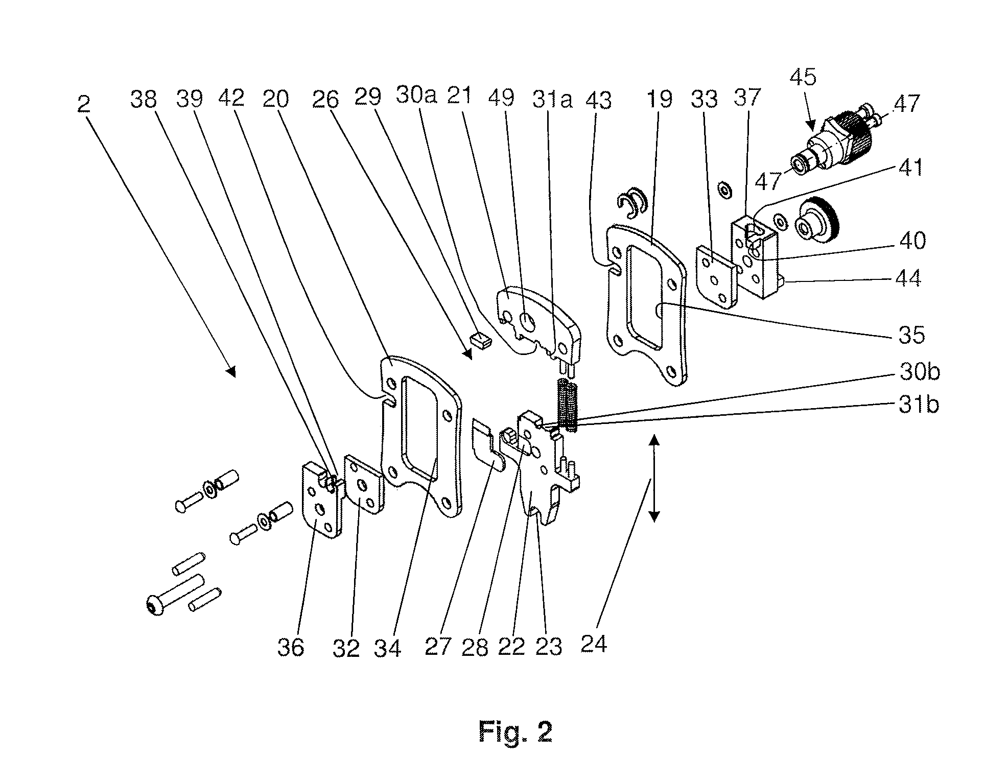
[0049]The embodiments of pliers shown in the figures are only examples for the type of pliers used, the kinematics used for producing the forces, the absolute and relative dimensions, the configuration of the cutting element, the position of the cutting element at the pliers and the linkage, the use and the type of the used automatic locking unit, the degrees of freedom of the movement of the head parts of the pliers, in particular the pivoting movement with the pivoting movement of the handles or a translational displacement activated by a pivoting movement of the handles, the configuration of the head part, the configuration of the built seat and the configuration of the cutting element itself. For giving only some examples for a variety of possible embodiments, the cutting element might be used in connection with a tool of the applicant according to the documents DE 40 23 337 C1, corresponding to U.S. Pat. No. 5,153,984 A; DE 44 27 553 A1; DE 100 56 900 C1, according to U.S. Pat....


PUM

PropertyMeasurementUnit
angleaaaaaaaaaa
drilling angleaaaaaaaaaa
translational degree of freedomaaaaaaaaaa

Abstract

The present invention relates to pliers for removing an insulating layer of an electrical cable, in particular a coaxial cable. The inventive pliers comprise a cutting element. The distance of the cutting element from a seat for the cable is adjustable. Furthermore, the cutting element has a degree of freedom in a circumferential direction of the coaxial cable relative to the seat.

Description

CROSS REFERENCE TO RELATED APPLICATIONS[0001]This application claims priority to co-pending German Patent Application No. DE 10 2007 038 626.7 entitled “Zange zum Abisolieren eines Kabels”, filed Aug. 16, 2007.FIELD OF THE INVENTION[0002]The present invention generally relates to pliers for partially removing the insulation of an electrical cable having a circular cross-section. A “cable” in the sense of the present invention is an electric conducting element with one or a plurality of wires wherein such cable comprises at least one layer, in particular a wire, core and / or an insulation that is rotationally symmetrical with respect to a longitudinal axis of the cable. It is also possible that a layer is built by a hollow cylindrical conducting element or a network or a braided conductor with a ring-like regular or irregular cross-section. The feature “cable” also covers wires, strands, braids, laces, flexes or any other types of conductive lines.[0003]One type of application of inve...

Claims


Application Information

Patent Timeline
Patent Type & Authority Applications(United States)
IPC IPC(8): B21F13/00B25F1/00
CPCH02G1/1221H01R43/0421
Inventor BATTENFELD, KURT
Owner WEZAG - WERKZEUGFAB
Why Eureka
Try Eureka